


Page 45
Revised 7/95 DFS-1 Manual
POWERTEC Ind. Corp.©
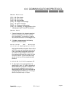
6.0 COMMUNICATIONS PROTOCOL
GENERAL DEFINITIONS:
[STX] - 02h - Start of data
[ETX] - 03h - End of data
[ACK] - 06h - Acknowledge
[NAK] - 15h - Negative Acknowledge
[DLE] - 10h - Data Link Escape
[CMD] -xxh - Command to be executed
[CSM] - xxh - Checksum, 2’s complement sum of the
data between the [STX] and [ETX] characters
GENERAL NOTES:
1. The use of brackets in this document means that
there is a single byte of information contained
within the brackets. This convention is used to
insure that the construction of the message is clear.
2. If the below message was sent, the following
checksum would be computed:
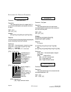
DLE STX UID CMD DATA DLE ETX CSM
[10] [02] [01] [82] [00][00][10][10][00] [10] [03] [6D]
Note the delimited datum character. Since a 10h is
the DLE, the only way the software can know that
a 10h in the middle of a data word is datum and
not the DLE is to put the datum in twice. The
driver software must know that a single 10h is the
DLE and not datum! The driver software must
actually use only one 10h to compute the check-
sum value.
01 + 82 + 00 + 00 + 10 + 00 = 93: 2’s complement = 6D
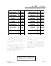
3. All data is sent in four bytes regardless of the
needed length of data. For instance, parameter 48
has the value of 0 for jump and 1 for MOP. The
actual parameter is passed in communications
however as a [00][00][00][00] for jump mode and
a [00][00][00][01] for MOP mode. In this way, all
data has an expected length of 4 bytes.