


Page 52
DFS-1 Manual Revised 7/95
POWERTEC Ind. Corp.©
Definitions:
[DIG] - Digital output number 01 to 04
[VL4] - Always 00
[VL3] - Always 00
[VL2] - Always 00
[VL1] - Status of output 00 = off 01 = on
[ERR] - Reported error
[80] - Unit not in remote mode
[84] - Illegal channel number
[86] - Illegal Command number
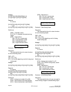
Write Digital Output (8C)
Command: Write Digital Output
Description:
This command tells the unit to turn on or off a
specific digital output contact.
CMD = [8C]
UID = [01] - [FF]
DIG = [01] - [04] depending on which Digital output
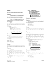
Message:
[DLE][STX][UID][CMD][DIG][VL4]
[VL3][VL2][VL1][DLE][ETX][CSM]
Response:
If no errors
[DLE][STX][UID][ACK][DLE][ETX][CSM]
else
[DLE][STX][UID][NAK][ERR][DLE][ETX][CSM]
Definitions:
[DIG] - Digital Output channel choice [00] thru
[04]
[VL4] - Always 00
[VL3] - Always 00
[VL2] - Always 00
[VL1] - [00] or [01] contact being open or
closed.
[ERR] - Reported Error
[80] - Unit not in remote mode
[84] - Illegal channel number
[85] - Illegal channel value
[86] - Illegal Command number
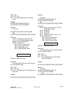
Set Operational Mode (8D)
Command: Set Operational Mode
Description:
This command tells the unit to turn on or off
specific input control functions such as run, stop, etc.
Refer to parameter 3 which defines which input
controls are allowed by communications link and
which MUST BE controlled by inputs on the terminal
strip. An error message will be produced if set mode
attempts to change the condition of an input that is
not allowed to be remotely changed.
CMD = [8D]
UID = [01] - [FF]
SMH = [00] - [FF]
SML = [00] - [FE]
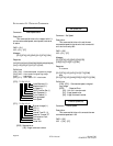
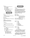
7 6 5 4 3 2 1 0—Bit Position
0 0 0 0 0 0 0 0—Bit value can be 0 (off) or 1 (on)
7 6 5 4 3 2 1 0—Digital input number
Note that input 1 is Estop which must always be
0 since this cannot be set remotely. This can ONLY
be a hardwired function. This means the largest
value for [00][00][SMH][SML] is [00][00][FF][FE].
Example: To turn on inputs 1 and 5 the value for
[00][00][SMH][SML] is 0000 0022, or [22]. Inputs
1 and 5 are defaulted to RUN and Reverse but can be
redefined in parameters 31 through 37.
depending on which CONTROL
INPUT SEE PARAMETER # 3 FOR
DEFINITION. This is a bit map that
defines the desired stateof each
control input as follows:
BIT PSN SML
where: 0 is Estop
1 is Run
2 is Preset
3 is Up input
4 is Down input
5 is Reverse mode
6 is Frequency mode
7 is Local/Remote (0 for local)
BIT PSN SMH
where: 0 is unused
1 is Jog
2 is Preset 2
3 is Contactor Aux