


Page 8
DFS-1 Manual Revised 7/95
POWERTEC Ind. Corp.©
MOTOR ENCODER CABLE:
The motor encoder cable is connected to plug-in
terminal strip TB1:A on the DFS-1 PC board. A
shielded cable must be used for the motor encoder
cable. The recommended cable is a 9-conductor
shielded cable (Belden Cable part # 9539 or equiva-
lent). The shield should be connected at the drive end
to the shield terminal (TB1:A1) and to terminal 10 (if
there is one) at the motor terminal strip and if not (as
on motors built prior to April 1992), the shield
should be cut off at the motor end and taped up.
The DFS-1 PC Board contains all of the func-
tions necessary to operate the Brushless DC motor
control according to the inputs connected to its
terminals and the programmed information in
memory. The DFS-1 board takes care of all speed,
torque, and control functions. It takes speed informa-
tion from the encoder, environmental information and
current (load) information from the power output
circuits of the drive, and compares all that informa-
tion to the input conditions and programmed param-
eters. It processes this information and turns the
power transistors on and off according to the needs of
the system.
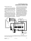
The DFS-1 is delivered with an installed set of
default parameters which will allow it to operate with
a standard set of connections (as illustrated in Figure
3) of the types used with standard motor controls.
However, these standard connections will not be in
the same physical positions as they are in the
standard control, and the default setting will not
take care of any optional modes of operation.
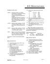
There are three plug-in terminal strips on the
bottom of the DFS-1 PC board labelled in sections
from left to right: TB1, TB2, and TB3. Though the
three sections look like two rows of strips, there is a
small separator between each of the sections. Each
of the sections has an upper row (A) and a lower row
(B). The B row is closest to the PC board. The
terminals are numbered consecutively from left to
right on each level.
ANALOG INPUTS:
There are two analog input ports to the DFS-1 on
TB1:B. When used as a voltage input, both of the
analog inputs are a differential type of input with a
minimum input impedance of 200 Kohms. When
using one of the analog inputs for a voltage input, the
input common at terminal 1 on TB1:B should be used
for shields.
When using an analog input as a milliamp input,
the (-) side of the input (terminal 4 for Analog Input
#1 or terminal 6 for Analog Input #2) should be
connected to the common of the milliamp current
source. The milliamp source should be connected to
the (+) input (terminal 3 for Analog Input #1 or
terminal 5 for Analog Input #2).
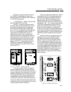
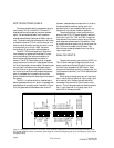
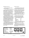
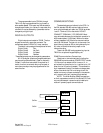
Figure 4: Assignments of the DFS-1 terminals. There are default assignments, but any of the analog and digital inputs
and outputs (except the motor connections, power supplies, commons, emergency stop input, and frequency input) may be
changed by setup.
+24V
Digital Out 1A
Digital Out 1B
Digital Out 2A
Digital Out 2B
Digital Out 3A
Digital Out 3B
Digital Out 4A
Digital Out 4B
FREQ REF OUT+
FREQ REF OUT-
Digital out COMMON
SPEED OUT
Speed Out COMMON
TB2
A
B
COMMON
Digital Input COMMON Cathodes
E-STOP
Digital In 1
Digital In 2
Digital In 3
Digital In 4
Digital In 5
Digital In 6
Digital In 7
FREQ REF IN+
FREQ IN-
FREQ REF SHIELD
+24V
DISPLAY POWER
DISPLAY +
DISPLAY-
Display COMMON
COMMUNICATIONS+
COMMUNICATIONS-
COMMUNICATIONS SHIELD
COMMUNICATIONS COMMON
Spacer
Spacer
TB3
A
B
Analog In COMMON
+10VDC
Analog In 1+
Analog In 1-
Analog In 2+
Analog In 2-
-10VREF
Analog Out 1+
Analog Out 2+
Analog Out COMMON
HALL SHIELD
HS1
HS3
HS2
HS4
HS5
HALL COMMON
HALL POWER
THERMAL
THERMAL POWER
TB1
A
B
Spacer
Spacer
1 2 3 4 5 6 7 8 9 10
1 2 3 4 5 6 7 8 9 10
1 2 3 4 5 6 7 8 9 10 11 12 13 14
1 2 3 4 5 6 7 8 9 10 11 12 13 14
1 2 3 4
1 2 3 4