


Page 10
DFS-1 Manual Revised 7/95
POWERTEC Ind. Corp.©
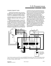
FREQUENCY OUTPUT:
There are two outputs available to supply a
frequency for external use.
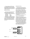
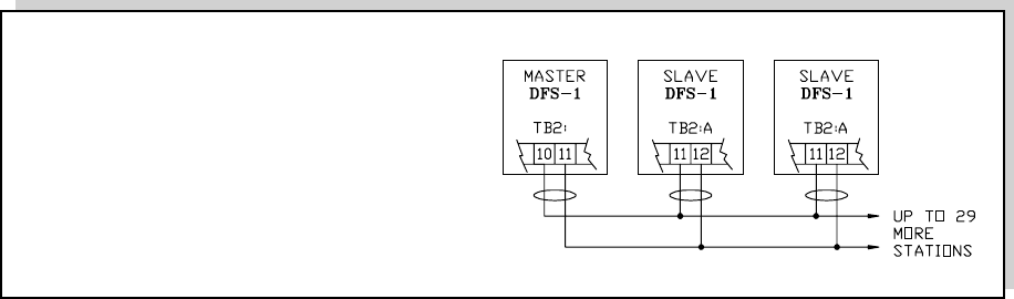
The first is located at TB2:B terminal 10 (+) and
11 (-). This is an output which is intended to provide
a reference frequency input for another DFS-1,
BCDMAX or CRM-1. This output is not compatible
with the DIGIMAX. It will provide a signal of +/-
1.5V minimum when connected to another DFS-1's
reference frequency input. This output on a unit
configured as a master, operates at 16 times the
frequency of the motor speed output reference. There
is a 120 ohm termination resistor built into the output
for transmission line termination.
When operating the DFS as a slave, the output
frequency is internally divided by 16 in addition to
being multiplied by the set ratio from the slave. As a
consequence, the frequency output from a DFS slave
cannot be used as the reference to another DFS slave
without some way of first multiplying this frequency
by 16. POWERTEC’s Cascade Ratio Multiplier
option board (4001-153430-XXX) can be used for
this purpose. Contact the factory for any frequency
following application which requires a reference
source other than a master DFS.
The other frequency output is at TB2:B13. This
is a 24VDC peak square wave referenced to the DFS-
1 common (TB2:B14). This signal is at the motor
speed output reference frequency and may be used
to interface with a DIGIMAX or a BLDC motor
control. This output sources a maximum of 10mA
and can sink 30mA.
DIGITAL INPUTS:
There are eight digital control inputs on TB2:A
as well as a +24VDC supply (TB2-A14) and com-
mon (TB2-A1). The eight inputs are optical isolator
input diodes with a common cathode connection at
TB2-A2. When the +24VDC, DFS-1 supply is used
to power the inputs, TB2:A2 must be jumpered to
the 24VDC common terminal on TB2:A1.
The functions of all inputs are programmable
except Emergency Stop (TB2-A3). All digital inputs
are electrically isolated from the DFS-1 power
supplies and common when an external power supply
is used to power the digital inputs (such as from a
PLC).
The default parameter setup is for a set of
standard motor controller input connections on
TB2:A terminal strip (see figure 3 on page 3).
Five of the inputs are set up for standard push-
button operation of the DFS-1. They are:
Run 4 (+)
Preset 5 (+)
UP (increase) 6 (+)
DOWN (decrease) 7 (+)
Reverse 8 (+)
All of these inputs are referred to TB2-A2. Note
that TB2-A2 (the common cathode connection) must
be jumpered to common (TB2:A1) in the basic
connections.
Each of these inputs will take a +24VDC input
(no more than 30VDC, not less than 18VDC). If an
external source of +24VDC is used, TB2-A2 on the
upper level must be connected to the negative side of
the external source.
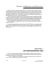
Figure 5: Slaving DFS-1 units with the Reference Frequency Output.
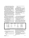
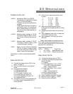
Mode of Operation: differential
Number of receivers: 32 maximum
Maximum Cable Length: 4000 feet
Maximum Frequency: 10 Megahertz
Common Mode Voltage: +12V, -7V
maximum
Driver Output: +/-1.5V minimum
Driver Load: 60 ohm minimum
Driver Short Circuit: 1 50 mA to ground
Driver Output Resistance: 120 ohms (ON)
Receiver Input Resistance: 12 Kohms
Receiver Sensitivity: +/-200 mA
B