


Page 1
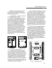
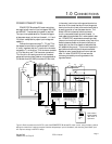
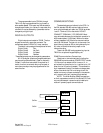
Figure 2: The Model 1000 chassis
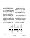
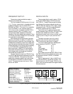
Figure 1: The DFS-1 replaces two boards.
If the board is being installed to replace the
boards on a standard control, unplug the strips on
TB1 and TB2, but do not disconnect any wires from
them yet. Unplug the 14-pin connector on P2 (at the
Base Driver Board) and the 10-pin connector on P3
(at the Capacitor Board). Remove these cables and
the Speed and Current controller boards from the
chassis and set them aside. Remove the studs at the
top right of where the Current Controller board was,
and at the top left of where the Speed Controller was
located ( the center studs - see figure 1).
1.0 INSTALLATION
The DFS-1 printed circuit board mounts on
any POWERTEC Brushless DC motor control
except the Model 500. The Model 1000 is used here
for illustration purposes only.
1.1 MOUNTING -- READ THIS ENTIRE
SECTION BEFORE STARTING!
The DFS-1 printed circuit board mounts on
the Model 1000 or Model 1000AR motor control in
place of both the Current Controller board (part
#141-108) and the Speed Controller board (part
#141-107 on the non-regenerative model 1000, part
# 147-101 on the regenerative model 1000AR).
These boards are mounted side by side on all
standard motor controls. TB1 is located on the
Current Controller (left hand board) and TB2 is on
the Speed Controller (right hand board). The first
eight connections which normally come into TB1
(the motor cable leads) will connect to the same
places on the DFS-1. The connections going into
TB2 (mainly operators and speed pot) on the
standard motor control will go to different connec-
tions on the DFS-1.
There are two flat ribbon cables which must be
connected from the DFS-1 to the other parts of the
motor control: one goes to the Base Driver Board
(part #141-105), and the other cable goes to the
Capacitor Board (part #141-106). See figure 2 for
the physical layout of the control and the location of
these boards. If the DFS-1 board is being installed
in the field, the cables should come with the new
board, since the connectors on the DFS-1 end are
different from the connectors on the Speed and
Current controller ends of the previous cables. Make
sure that you have these new cables before proceed-
ing to install the board. If you do not have them, call
POWERTEC's service department before proceed-
ing.
The DFS-1 board may be used as either a non-
regenerative control or as a regenerative control.
This selection is made by one of its parameter
settings. The DFS-1 may be installed on a Model
1000 non-regenerative brushless DC control, but if
the unit is to be used for a regenerative application,
a bus loader of the appropriate voltage and resistors
of sufficient wattage must be added before the drive
may be used regeneratively. If a bus loader is not
installed before regenerative operation occurs, it is
likely that the control will trip out repeatedly. A
Model 1000AR will already have a bus loader and
resistors attached.