


Page 16
DFS-1 Manual Revised 7/95
POWERTEC Ind. Corp.©
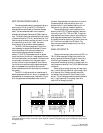
FREQUENCY INPUTS AND
OUTPUTS
There is one frequency input and there are two
frequency outputs available.
INPUT
#1 REFERENCE FREQUENCY INPUT
TB2:A Terminals 11 (+) and 12 (-).
• This is a line receiver type input which must be
driven by a differential line driver output.
• This frequency input requires a frequency 16
times the feedback from the motor.
• The feedback from the motor is normally 120
PPR for 4 pole motors and 240 PPR for 8 pole
motors.
• Normal input is 56 Kilohertz for 0 to full speed
for a 1750 RPM motor with a 120ppr encoder.
• Terminal 13 is for the shield. Do not ground
terminal 13 directly. It is internally terminated.
OUTPUTS
#1 REFERENCE FREQUENCY OUTPUT
TB2:B Terminals 10 (+) and 11 (-),
• This is a differential line driver output which
must be used with a differential line driver input.
• This frequency output is 16 times the reference
frequency to the motor.
• This output may drive up to 32 receivers.
• Connect the shield to terminal 12. This will
ground the shield internally.
#2 MOTOR SPEED FREQUENCY OUTPUT
TB2:B Terminals 13 (+) and 14 (common),
• This output is a +24VDC peak square wave at
the motor feedback pulse rate, which is 2 times
RPM for 4 pole motors and 4 times RPM for 8
pole motors.
The reference frequency input and output are
capable of receiving and sending at up to 1 Mega-
hertz.
Motor Speed output emits frequencies up to 100
Kilohertz.
DIGITAL INPUTS
The eight digital inputs of the DFS-1 are
optically coupled requiring +24VDC (+/-6VDC) at
about 5mA each. These inputs are isolated from the
common of the board.
All inputs are programmable as to function,
EXCEPT the EMERGENCY STOP input. Inputs #1
through #7 may be assigned as general purpose
inputs.
The defaults are as follows:
TB2:A terminal 3(+) Emergency Stop
(Cannot be reassigned)
DI 1. TB2:A4(+) Run
DI 2. TB2:A5(+) Preset Speed
DI 3. TB2:A6(+) Up (Increase)
DI 4. TB2:A7(+) Down (Decrease)
DI 5. TB2:A8(+) Reverse
DI 6. TB2:A9(+) Frequency Mode
DI 7. TB2:A10(+) Local/Remote
Inputs #1 through #7 may also be programmed
for inverted input, i.e., active when input is low.
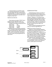
DIGITAL OUTPUTS
There are four dry contact outputs from the
DFS-1. All of these outputs are on TB2:B. All
outputs are programmable as to function, and all
outputs may be set up as either normally open or
normally closed.
Each relay output has a single, isolated, contact
output which may be programmed as normally open
or normally closed, with the contact rated at 1 Amp,
125VAC resistive.
The default assignments are as follows:
DO 1. TB2:B terminals 2 and 3 Run relay contact
Closed while running
DO 2. TB2:B terminals 4 and 5 No fault relay
Closed while no faults
DO 3. TB2:B terminals 6 and 7 At Speed relay
Closed when at speed
DO 4. TB2:B terminals 8 and 9 Remote Mode
Closed when in Remote