


Page 54
DFS-1 Manual Revised 7/95
POWERTEC Ind. Corp.©
Application Mode (8F)
Command: Application Mode Command
Description:
This command reads/sets the operating setpoint
by communications rather than using an analog input
for the setpoint when a special application mode is
active (see parameter 5). The modes currently
defined are shown below. It is possible in the future
that additional application modes may be added.
CMD = [8F]
UID = [01] - [FF]
AMD = [20],[21],[22],[23],[30],[31],[32]
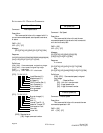
Message:
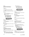
[DLE][STX][UID][CMD][AMD][VL4]
[VL3][VL2][VL1][DLE][ETX][CSM]
Response:
If no errors,
[DLE][STX][UID][ACK][DLE][ETX][CSM]
else,
[DLE][STX][UID][NAK][ERR][DLE][ETX][CSM]
Definitions:
[AMD] - Application Mode
[20] - Set Motoring torque setpoint
[21] - Set Regen torque setpoint
[22] - Set Horsepower setpoint
[23] - Set Speed/Ratio with ramp rate
[30] - Read Motoring Torque Setpoint
[31] - Read Regen Torque Setpoint
[32] - Read Horsepower Setpoint
[VL4] - Depends on value passed
[VL3] - Depends on value passed
[VL2] - Depends on value passed
[VL1] - Depends on value passed
[ERR] - Reported Error
[80] - Unit not in remote
[82] - Illegal parameter number
[86] - Illegal Command number
[89] - Illegal Application value
[8A] - Illegal Application
An error message [8A] will be sent if a setpoint
for horsepower [22] for instance is sent when
parameter 5 is set to allow motoring torque limit, or
any other mode than horsepower.
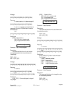
Examples:
[20] Motoring Torque setpoint can be 0 to 1000 (hex
3E8) where torque is set in tenths of percent
(1000 equals 100.0%) A torque of 100.0%
would then be sent as [00][00][03][E8].
[21] Regen Torque same description as above
[22] Horsepower setpoint has the same description
as torque where hp is set in tenths of percent,
100% maximum
[23] Set speed/ratio with accel and decel ramp.
This is used whenever a temporary setpoint for
speed is desired and the ramp up and down rates
are different from those in the parameter table.
This setpoint and ramp rate is temporary and the
drive will revert automatically back to the
normal setpoint and ramp rates on any succes-
sive commands. Speed/ratio requires 4 bytes,
accel requires 4 bytes and decel requires 4 bytes.
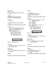
For instance a complete message including the
header, etc. for a speed of 1400 rpm and accel
rate of 10 seconds and decel rate of 5 seconds to
unit # 5 would be:
[10][02][05][8F[23][00][00][05][78][00][00]
[00][0A][00][00][00][05][10][03][CSM]
ATTACHMENT B:
PARAMETER DESCRIPTION:
Following is a list of the parameters for the DFS-
1. All parameters are 4 byte values regardless of the
data. For instance, parameter 5 is master slave and
can be only [00] or [01] but the data bytes required
for the parameter are [00][00][00][01] or
[00][00][00][00]. This is done to keep communica-
tions simple when dealing with parameter informa-
tion, especially with any packed message.
59 through 63 are general use parameters for
future use and not currently defined.
80 through 95 are special use parameters for
future use and not currently defined.