


276 Fabric OS Administrator’s Guide
53-1002745-02
Logical switch overview
10
This chapter describes the logical switch and logical fabric features. For information about device
sharing with Virtual Fabrics, refer to “FC-FC routing and Virtual Fabrics” on page 606.
For information about supported switches and port types, refer to “Supported platforms for
Virtual Fabrics” on page 286.
Virtual Fabrics and Admin Domains are mutually exclusive and are not supported at the same time
on a switch.
NOTE
A note on terminology: Virtual Fabrics is the name of the suite of features. A logical fabric is a type
of fabric that you can create using the Virtual Fabrics suite of features.
Logical switch overview
Traditionally, each switch and all the ports in the switch act as a single Fibre Channel switch (FC
switch) that participates in a single fabric. The logical switch feature allows you to divide a physical
chassis into multiple fabric elements. Each of these fabric elements is referred to as a logical
switch. Each logical switch functions as an independent self-contained FC switch.
NOTE
Each chassis can have multiple logical switches.
Default logical switch
To use the Virtual Fabrics features, you must first enable Virtual Fabrics on the switch. Enabling
Virtual Fabrics creates a single logical switch in the physical chassis. This logical switch is called
the default logical switch, and it initially contains all of the ports in the physical chassis.
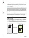
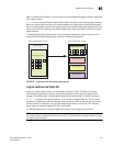
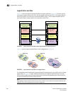
Figure 17 shows a switch before and after enabling Virtual Fabrics. In this example, the switch has
10 ports, labeled P0 through P9.
FIGURE 17 Switch before and after enabling Virtual Fabrics
Before enabling Virtual Fabrics After enabling Virtual Fabrics
Physical chassis
Default logical switch
Physical chassis
P9P0
P1
P2
P4
P3
P2
P1
P0
P3
P4
P5
P6
P7
P8
P9
P8
P7
P5
P6