


278 Fabric OS Administrator’s Guide
53-1002745-02
Logical switch overview
10
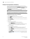
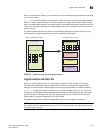
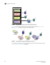
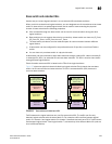
FIGURE 19 Fabric IDs assigned to logical switches
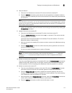
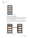
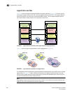
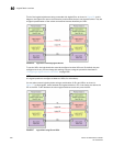
Port assignment in logical switches
Initially, all ports belong to the default logical switch. When you create additional logical switches,
they are empty and you must assign ports to those logical switches. As you assign ports to a logical
switch, the ports are moved from the default logical switch to the newly created logical switch.
A given port can be in only one logical switch.
In Figure 20, the default logical switch initially has 10 ports, labeled P0 through P9. After logical
switches are created, the ports are assigned to specific logical switches. Note that ports 0, 1, 7,
and 8 have not been assigned to a logical switch and so remain assigned to the default logical
switch.
FIGURE 20 Assigning ports to logical switches
Logical switch 5
(FID = 20)
Physical chassis
Logical switch 1
(Default logical switch)
(FID = 128)
Logical switch 2
(FID = 1)
Logical switch 3
(FID = 15)
Logical switch 4
(FID = 8)
Before port assignment After port assignment
Logical switch 2
Logical switch 4
Logical switch 3
P4
P3
P2
P1
P0
P9
P8
P7P5
P6
Logical switch 4
P6
Logical switch 3
P5
P4
Logical switch 2
P3
P2
Logical switch 1
(Default logical switch)
P0
P9
P8P7P1
Logical switch 1
(Default logical switch)