


Fabric OS Administrator’s Guide 495
53-1002745-02
Supported topologies for ICL connections
19
Supported topologies for ICL connections
You can connect the Brocade Backbones in a mesh topology and a core-edge topology. A brief
description of each follows. (You can also connect two DCX 8510s point-to-point.)
The illustrations in this section show sample topologies. Refer to the Brocade SAN Scalability
Guidelines for details about maximum topology configurations.
Mesh topology
You can connect the Brocade Backbones in a mesh topology, in which every chassis is connected
to every other chassis.
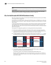
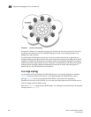
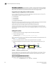
A simple form of the mesh topology is the triangular topology (shown in Figure 61). The triangular
topology is supported by three Brocade Backbone chassis. The chassis for each topology must all
be from the same family:
• Brocade DCX Backbone family (DCX or DCX-4S)
• Brocade DCX 8510 Backbone family (DCX 8510-8 or DCX 8510-4)
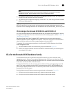
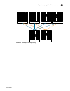
Another form is the full nine-mesh topology shown in Figure 62. This topology is supported by DCX
8510-8 Backbones only. (You can use DCX 8510-4 Backbones for a five-mesh topology.)
FIGURE 61 ICL triangular topology with Brocade DCX 8510-8 chassis