


Fabric OS Administrator’s Guide 279
53-1002745-02
Logical switch overview
10
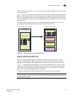
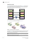
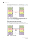
A given port is always in one (and only one) logical switch. The following scenarios refer to the
chassis after port assignment in Figure 20:
• If you assign P2 to logical switch 2, you cannot assign P2 to any other logical switch.
• If you want to remove a port from a logical switch, you cannot delete it from the logical switch,
but must move it to a different logical switch. For example, if you want to remove P4 from
logical switch 3, you must assign it to a different logical switch: logical switch 2, logical
switch 4, or logical switch 1 (the default logical switch).
•
If you assign a port to a logical switch, it is removed automatically from the logical switch it is
currently in. If you assign P3 to Logical switch 3, P3 is automatically removed from logical switch 2.
• If you do not assign a port to any logical switch, it remains in the default logical switch, as is the
case with ports 0, 1, 7, and 8.
Refer to “Adding and moving ports on a logical switch” on page 295 for instructions for assigning
and moving ports on logical switches.
A logical switch can have as many ports as are available in the chassis. In Figure 20, the chassis
has 10 ports. You could assign all 10 ports to a single logical switch, such as logical switch 2; if you
did this, however, no ports would be available for logical switches 3 and 4.
You can move only F_Ports and E_Ports from one logical switch to another. If you want to configure
a different type of port, such as a VE_Port or EX_Port, you must configure them after you move
them. Some types of ports cannot be moved from the default logical switch. Refer to “Supported
platforms for Virtual Fabrics” on page 286 for detailed information about these ports.
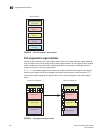
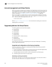
Logical switches and connected devices
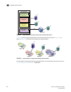
You can connect devices to logical switches, as shown in Figure 21 on page 280. In logical
switch 2, P2 is an F_Port that is connected to H1. In logical switch 3, P4 is an F_Port that is
connected to D1. H1 and D1 cannot communicate with each other because they are in different
fabrics, even though they are both connected to the same physical chassis.
You can also connect other switches to logical switches. In Figure 21, P6 is an E_Port that forms an
inter-switch link (ISL) between logical switch 4 and the non-Virtual Fabrics switch. Logical switch 4
is the only logical switch that can communicate with the non-Virtual Fabrics switch and D2,
because the other logical switches are in different fabrics.