


Fabric OS Administrator’s Guide 607
53-1002745-02
FC-FC routing and Virtual Fabrics
24
• Although the Brocade 6510 and 6520 supports up to four logical switches, if you are using
FC-FC routing, they can have a maximum of three logical switches.
Logical switch configuration for FC routing
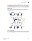
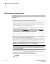
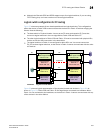
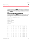
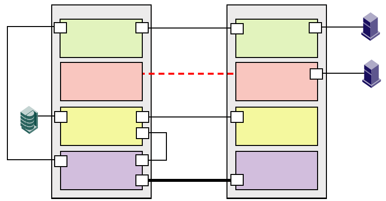
Figure 82 shows an example of two chassis partitioned into logical switches. This configuration
allows the device in Fabric 128 to communicate with the device in Fabric 15 without merging the
fabrics. Note the following:
• The base switch in Physical chassis 1 serves as an FC router and contains EX_Ports that
connect to logical switches in the two edge fabrics, Fabric 128 and Fabric 15.
• The other logical switches in Fabric 128 and Fabric 15 must be connected with physical ISLs,
and do not use the XISL connection in the base fabric.
• The logical switches in Fabric 1 are configured to allow XISL use. You cannot connect an
EX_Port to these logical switches, so the device in Fabric 1 cannot communicate with the other
two devices.
FIGURE 82 EX_Ports in a base switch
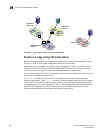
Figure 83 shows a logical representation of the physical chassis and devices in Figure 82. As
shown in Figure 83, Fabric 128 and Fabric 15 are edge fabrics connected to a backbone fabric.
Fabric 1 is not connected to the backbone, so the device in Fabric 1 cannot communicate with any
of the devices in the other fabrics.
Logical switch 8
(Base switch)
Fabric ID 8
Logical switch 7
Fabric ID 15
Logical switch 6
Fabric ID 1
Allows XISL use
Logical switch 5
(Default logical switch)
Fabric ID 128
Physical chassis 2
Logical switch 4
(Base switch)
Fabric ID 8
E
Logical switch 3
Fabric ID 15
E
Logical switch 2
Fabric ID 1
Allows XISL use
E
Logical switch 1
(Default logical switch)
Fabric ID 128
E
Physical chassis 1
E
E
E
XISL
EX
EX
F
F
E
IFL
IFL
ISL
ISL
Logical ISL
F