


282 Fabric OS Administrator’s Guide
53-1002745-02
Logical fabric overview
10
Logical fabric and ISLs
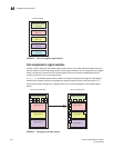
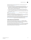
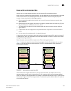
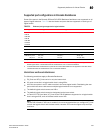
Figure 23 shows two physical chassis divided into logical switches. In Figure 23, ISLs are used to
connect the logical switches with FID 1 and the logical switches with FID 15. The logical switches
with FID 8 are each connected to a non-Virtual Fabrics switch. The two logical switches and the
non-Virtual Fabrics switch are all in the same fabric, with FID 8.
FIGURE 23 Logical switches connected to other logical switches through physical ISLs
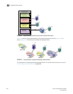
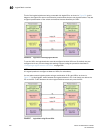
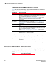
Figure 24 shows a logical representation of the configuration in Figure 23.
FIGURE 24 Logical switches connected to form logical fabrics
The ISLs between the logical switches are dedicated ISLs because they carry traffic only for a single
logical fabric. In Figure 23, Fabric 128 has two switches (the default logical switches), but they
cannot communicate with each other because they have no ISLs between them and they cannot
use the ISLs between the other logical switches.
NOTE
Only logical switches with the same FID can form a fabric. If you connect two logical switches with
different FIDs, the link between the switches segments.
Logical switch 8
Fabric ID 8
P9
Logical switch 7
Fabric ID 15
P7
Logical switch 6
Fabric ID 1
P4
Physical chassis 2
P8
P6
P5
P3
P2
P1
Switch
Logical switch 4
Fabric ID 8
P6
Logical switch 3
Fabric ID 15
P5
P4
Logical switch 2
Fabric ID 1
P3
P2
Logical switch 1
(Default logical switch)
Fabric ID 128
P1
Physical chassis 1
Logical switch 5
(Default logical switch)
Fabric ID 128
Fabric 128
Fabric 1
Fabric 15
Fabric 8
SW1
SW8
SW4
SW7
SW3
SW6
SW2
SW5