


2. WIRING
2-4
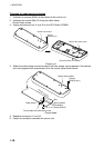
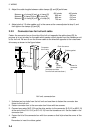
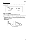
3. Adjust the cable lengths between cable clamps [A] and [B] as follows:
Between a of clamp [A] and a of clamp [B]
Between i of clamp [A] and i of clamp [B]
Between w of clamp [A] and w of clamp [B]
600 stroke
660 mm
690 mm
720 mm
400 stroke
580 mm
610 mm
640 mm
4. Adjust slack of 12 other cables so it is the same as the ones adjusted at step 3, and
then tighten the clamps [A] and [B].
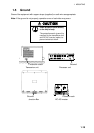
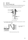
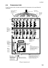
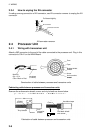
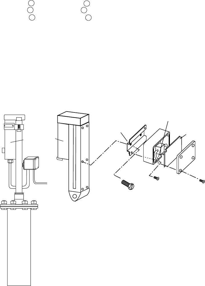
2.2.2 Connector box for hull unit cable
Fasten the connector box on the side of the hull unit opposite the cable clamp [B]. Its
purpose is to act as relay for the cable which sends control signals from the transducer unit
to the hull unit. Be sure to run the thinner cable to the direction opposite to the raise/lower
drive assy as shown in the figure below.
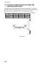
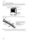
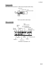
S-10-15-5/10
Drive unit
Rubber gasket
Connector
box fixture
Hex bolt
(Unfasten two bolts
from hull unit and use them.)
Screw
(M4X10)
Screw for
connector
box
Pinch the armor.
Hull unit, connector box
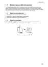
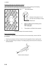
1. Unfasten two hex bolts from the hull unit and use them to fasten the connector box
fixture to the hull unit.
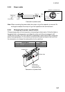
2. Fasten connector box to the connector box fixture with two screws.
3. Connect connector MLP-15 from the drive section to the connector ELR-15 (or MLR-15)
at the end of the S10-15-5 (or S10-15-10) from the transducer unit. Set the cable in the
connector box.
4. Fasten the lid of the connector box with four screws so that lid pinches the armor of the
cable.
Remember to insert the rubber gasket.