


2. WIRING
2-19
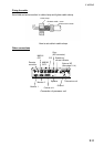
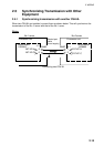
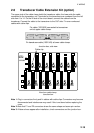
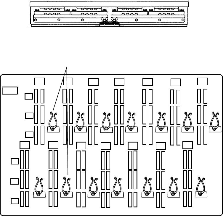
2.6 Transducer Cable Extension Kit (option)
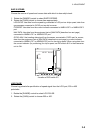
The upper side of the cable clamp holds the transducer cable; the lower side the cable
connected to the transceiver unit. Terminals for the transducer are numbered from the left
side from 1 to 14. On the IN side of the circuit board, connect the cables from the
transducer. Connect the cable to the transceiver to the OUT side. Fix even-numbered
cables with cable clips.
Fix cable (10S1950) connected to transceiver
unit at upper cable clamp.
Fix transducer cable (10S1943) at lower cable clamp.
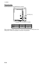
Junction box, side view
XCB
10P6865
TRX2
TRX1
TRX4
TRX3
TRX6
TRX5
TRX8
TRX7
TRX10
TRX9
TRX12
TRX11
TRX14
TRX13
IN OUT
IN OUT
IN OUT
IN OUT
IN OUT
IN OUT
IN OUT
IN OUT
IN OUT
IN OUT
IN OUT
IN OUT
IN OUT
IN OUT
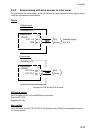
P1
P2
P3
P1
P2
P3
View from cable clamp
Cable clip
Junction box
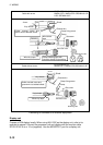
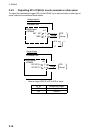
Note 1: Plug in connectors firmly and fix cables with cable clips. Connectors may become
disconnected and interference may result if this is not done before replacing the
cover.
Note 2: Note that P1 and P2 connectors share the same shape and same pin number.
Note 3: If false echoes appear after installation, check connectors and the junction box.