


Modbus and I/O Data
28 312785C
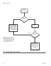
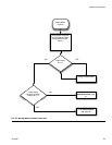
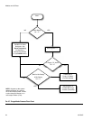
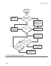
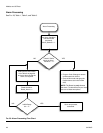
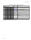
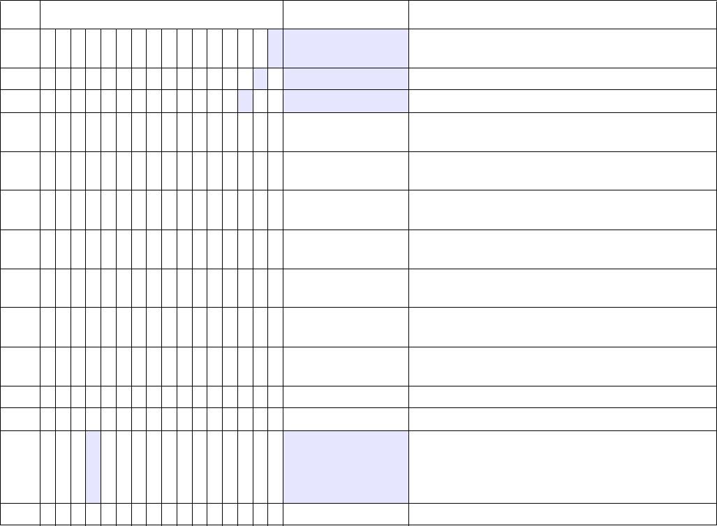
NOTE: Shaded cells relate to the flow charts on pages 23-26.
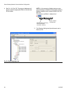
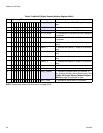
Table 2: ProMix 2KS Digital Outputs (Modbus Register 40041)
Bit Digital Input Binary Name Details
0 000000000000000
1 Purge_CC_Active “1” indicates Purge or Color Change is in prog-
ress
1 00000000000000
10Mix_Active “1” indicates Mix is in progress
2 0000000000000
100Mix_Ready “1” indicates No Alarms and OK to Mix
3 0000000000001000CC_Fill_Active “1” indicates the Fill portion of a Color Change is
in progress
4 0000000000010000FCalActive “1” indicates the Flow Control Calibrate routine is
in progress
5 0000000000100000Flow_Rate_Alarm “1” indicates the Flow Rate Alarm/Warning is
active
6 0000000001000000Special_1 “1” indicates the Special_1 output is on (monitor
only)
7 0000000010000000Special_2 “1” indicates the Special_2 output is on (monitor
only)
8 0000000100000000Special_3 “1” indicates the Special_3 output is on (monitor
only)
9 0000001000000000Special_4 “1” indicates the Special_4 output is on (monitor
only)
10 0000010000000000Not Used
11 0000100000000000Not Used
12 0 0 0
1000000000000Alarm_General “1” indicates a General Alarm is in process. (If
Mix_Active is still High, then a Warning only.) See
ProMix 2KS Active Alarms (Modbus Register
40010) on page 29 for details on type.
13 0010000000000000Alarm_Potlife “1” indicates a Potlife Alarm is in process.