


Appendix A: DeviceNet
™
Slave Communication
50 312785C
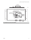
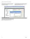
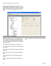
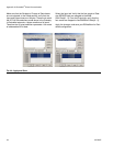
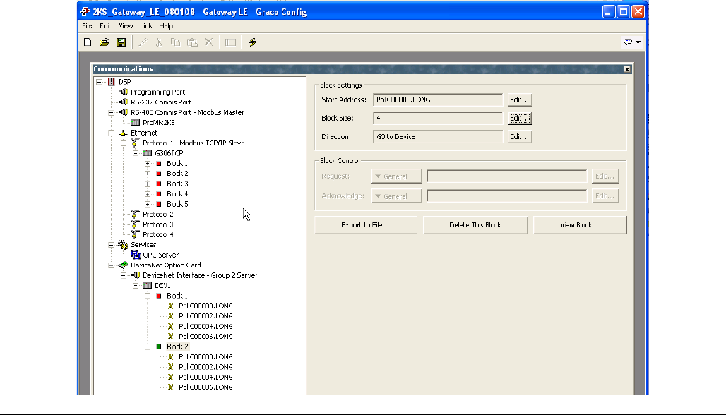
Select the second Gateway Block and set it up for I/O
Polled Response Data 00000, with a length of 4, and the
Direction Gateway To Device. This will be the Write Data
Block. F
IG. 36 shows both Gateway blocks once com-
pleted.
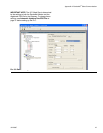
NOTE: Read and Write are from the Gateway point of
view. This means the master can send data in Block A,
so the Gateway can read data. On the other hand, the
master can only pull data from Block B, so the Gateway
can only write data.
The addressing scheme available is outlined below:
BitC – Identifies the I/O Bit-Strobe command data (Mas-
ter to Slave).
BitR – Identifies the I/O Bit-Strobe response data (Slave
to Master).
PollC – Identifies the I/O Poll command data (Master to
Slave).
PollR – Identifies the I/O Poll response data (Slave to
Master).
DataC – Identifies the I/O Consumed Data (Master to
Slave).
DataP – Identifies the I/O Produced Data (Slave to Mas-
ter).
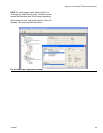
F
IG. 36: DeviceNet Block Mapping