


Appendix A: DeviceNet
™
Slave Communication
56 312785C
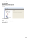
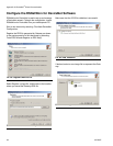
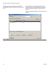
Configure the DeviceNet Scanner to be address 0.
Make sure to set up the 32-bit Input and Output memory
spaces for a size of 32 (to match the configuration made
above in both Gateway and RSNetWorx for DeviceNet).
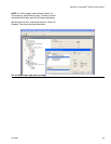
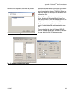
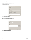
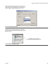
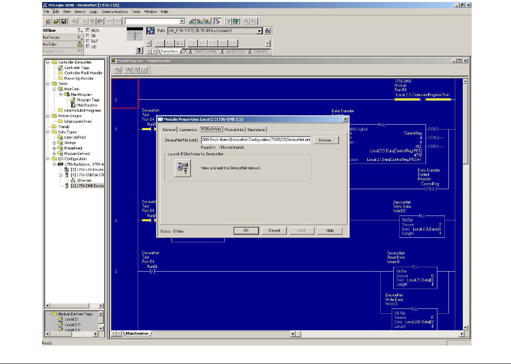
Select the RSNetWorx tab, and navigate to the RSNet-
Worx for DeviceNet configuration that you have previ-
ously created. Open the configuration from here and
download it to the network.
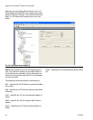
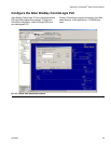
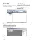
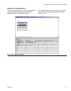
In the Main Task tree, open the Main Routine Ladder
Logic file. Create a rung of ladder to enable the Devi-
ceNet network. The required output is always:
Local:YourDNBSlot:0.CommandRegister.Run
Create a few rungs by taking the DeviceNet Input data,
Local:2:I.Data[0…3], and adding 1 to them. Store the
results in Local:2:O.Data[0…3]. Based on the configura-
tion in the Gateway, if values are changed on the Gate-
way Write tags, the Read tags will display the respective
values, plus one.
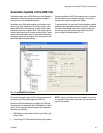
Save and download this configuration to the Control-
Logix PLC.
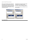
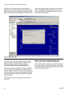
Wire the DeviceNet Network
All DeviceNet networks require a termination resistor at
the two end nodes on the network. Place a ¼ watt 120
ohm resistor between CAN H (White) and CAN L (Blue)
of the DeviceNet connection.
F
IG. 46: Main Task Tree