


System Description 11
Peripherals
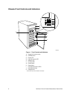
External Bay for 5.25-inch Removable Media Devices
The chassis has a bay for two 5.25-inch half-height peripherals that is accessible from the front of
the system. This bay is intended to provide space for CD-ROM, tape backup or other removable
devices.
You can convert the 5.25-inch bays to a single full-height bay. We recommend that you do not use
this bay for hard disk drives, because they generate EMI, ESD susceptibility increases, and the
drive will not be adequately cooled.
Internal Bay for 3.5-inch IDE Hard Drives
The chassis has a 3.5-inch bay for two half-height or 1-inch high IDE hard drives. The bay is not
externally accessible.
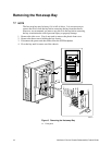
Hot-swap Bay
A hot-swap bay is provided for five SCSI SCA2 hard drives that are 3.5 inches wide and 1 inch
high. The bay is designed for drives that consume up to 17 watts of power each. Drives must be
specified to run at a maximum ambient temperature of 50 C.
The system was designed to allow the user to install a Redundant Array of Independent Disks
(RAID). A software implementation with onboard SCSI or an add-in RAID controller card can be
used to set up RAID applications.
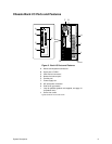
SCSI Hot-swap Backplane
The hot-swap backplane provides the following:
Five Single Connector Assembly (SCA2) connectors for SCA2-compatible SCSI drives
Power control for each drive, including automatic slot-power-down upon removing a drive
Signal for a fault indicator on the front panel for each drive
Internal IMB (Intelligent Management Bus)
Two +12 V connectors for a fan with tachometer
Local IMB-based temperature sensor
The SCSI hot-swap backplane provides control signals and power for five Ultra2/LVD 3.5-inch,
1-inch high, SCA2 SCSI hard disk drives. The backplane receives control signals from the SCSI
controller on the server board through a cable connected to the wide SCSI connector on the
backplane. The backplane is powered through cables connected to the two power connectors.
The drives get their control signals and power from the SCA2 connectors on the backplane.
The fault indicators on the front panel indicate failure status for each drive in the bay. These
indicators get their signals through a cable connected to the front panel connector on the
backplane.