


Working Inside the System 27
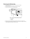
Hard Drives
Drive Cabling Considerations
The number of devices you can install depends on:
The number supported by the bus
The number of physical drive bays available
The combination of SCSI and IDE devices
You should route cables to minimize airflow disruption. Air flows from the front to the rear of the
chassis. You should route IDE and diskette drive cables behind the hot-swap bay.
IDE Requirements
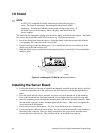
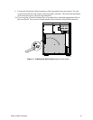
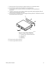
An 18-inch long IDE cable that supports two drives is standard in the system.
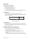
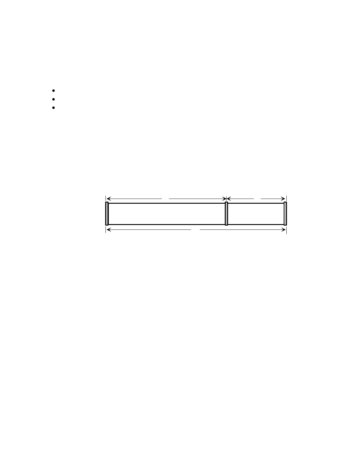
For proper IDE operation, note the cable length specified in the following figure. If no drives are
present on an IDE channel, the cable must be removed. If only one drive is installed, it must be
connected at the end of the cable.
12" 6"
18"
OM05093
Baseboard Drive 1 Drive 0
Figure 15. IDE Cable Dimensions
SCSI Requirements
All SCSI devices must be unterminated except the peripheral at the end of the SCSI cable. Hard
drives usually provide an active termination, while CD-ROM drives do not. The SCSI controller
on the server board is actively terminated. The SCSI hot-swap backplane provides termination and
SCSI IDs for drives connected to it.
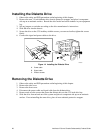
Installing a Hard Drive into the IDE drive bay
The IDE drive bay provides space for two 1-inch high hard drives.
1. Observe the safety and ESD precautions at the beginning of this chapter.
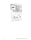
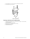
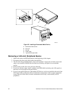
2. Remove the IDE drive bay from the chassis.
3. Remove the drive from its protective wrapper, and place it on an antistatic surface.
4. Record the drive model and serial numbers in your equipment log.
5. Set any jumpers and/or switches on the drive according to the drive manufacturer’s
instructions.
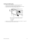
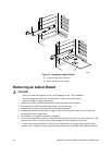
6. Slide the drive into the drive bay so the screw holes in the drive and the bay line up. For the
best cooling, the component side of the drive should face away from the plate of the drive bay.