


Working Inside the System 33
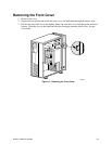
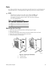
Installing the Front Cover
1. Insert the plastic tabs on the front cover into the slots on the right of the chassis. Squeeze the
front panel and chassis together along the left side until the plastic tabs snap into their slots.
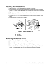
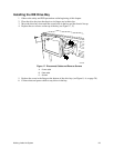
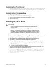
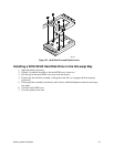
Installing the Hot-swap Bay
1. Tilt the bay into the chassis.
2. Connect the power and data cables to the SCSI backplane.
3. Install and tighten the three screws holding the bay to the chassis.
4. Install the side cover.
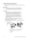
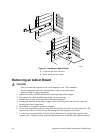
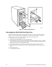
Installing an Add-in Board
CAUTIONS
Do not overload the server board by installing add-in boards that draw
excessive current.
Add-in boards can be extremely sensitive to ESD and always require careful
handling. After removing the board from its protective wrapper or from the
server board, place it component side up on a grounded, static free surface or
conductive foam pad—if available. Do not slide the board over any surface.
1. Remove side cover.
2. Remove and save the expansion slot screw and cover.
3. Remove add-in board from its protective wrapper. Be careful not to touch the components or
gold edge connectors. Place board component side up on an antistatic surface.
4. Record the type and serial number of the add-in board in your equipment log.
5. Set jumpers or switches according to the manufacturer’s instructions.
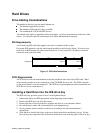
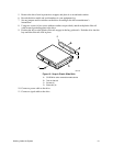
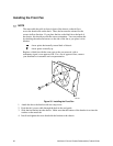
6. Hold board by its top edge or upper corners. Firmly press it into an expansion slot on the
server board. The tapered foot of the board retaining bracket must fit into the mating slot in
the expansion slot frame.
Install an ISA board component side UP.
Install a PCI board component side DOWN.
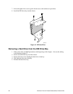
7. Align the rounded notch in the retaining bracket with the threaded hole in the frame. The
bracket fits the space that was occupied by the slot cover.
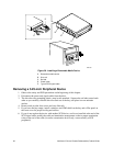
8. Use the screw removed earlier. Insert it into the threaded hole, and push the rounded notch
against the screw. Tighten it firmly to prevent the bracket from interfering with adjacent
brackets. Attach cables if necessary.
9. Reinstall the side cover.