


7
Installation of the inverters and precautions
2.2 Installation of the inverters and precautions
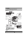
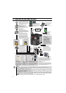
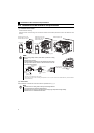
(1) Installation of the inverter
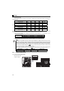
Enclosure surface mounting
Remove the front cover and wiring cover to mount the inverter to the surface. (Remove the covers in the directions of the
arrows.)
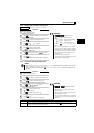
(2) Environment
Before installation, check that the environment meets the specifications on page 41.
NOTE
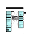
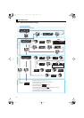
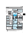
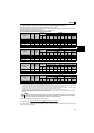
y When encasing multiple inverters, install them in parallel as a cooling
measure.
y Install the inverter vertically.
y For heat dissipation and maintenance, allow minimum clearance shown
in the figures below from the inverter to the other devices and to the
inner surface of the enclosure.
∗1 Allow 5cm or more clearance for 5.5K or higher.
∗2 When using the inverters at the surrounding air temperature of 40°C or less, the inverters can be installed without any clearance between
them (0cm clearance).
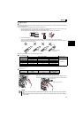
Note
y Install the inverter on a strong surface securely and vertically with bolts.
y Leave enough clearances and take cooling measures.
y Avoid places where the inverter is subjected to direct sunlight, high temperature and high humidity.
y Install the inverter on a nonflammable wall surface.
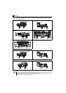
Front cover
Front cover
Front cover
Wiring cover Wiring cover
FR-D720-0.1K to 0.75K
FR-D720S-0.1K to 0.75K
FR-D710W-0.1K to 0.4K
FR-D720-1.5K to 3.7K
FR-D740-0.4K to 3.7K
FR-D720S-1.5K, 2.2K
FR-D710W-0.75K
FR-D720-5.5K to 15K
FR-D740-5.5K to 15K
Refer to the clearances below.
10cm or more
10cm or more
Measurement
position
Measurement
position
5cm
5cm
5cm
-10 C to 50 C
(non-freezing)
1cm or
more
∗1, ∗2
1cm or
more
∗1, ∗2
1cm or
more
∗1