


12
Wiring
2
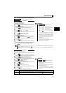
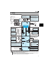
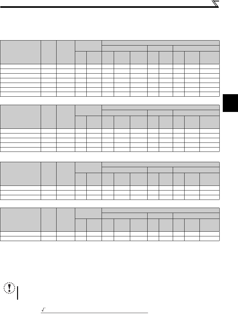
(1) Cable sizes etc., of the main control circuit terminals and earth (ground) terminals
Select the recommended cable size to ensure that a voltage drop will be 2% or less.
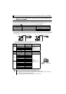
If the wiring distance is long between the inverter and motor, a main circuit cable voltage drop will cause the motor torque to
decrease especially at the output of a low frequency.
The following table indicates a selection example for the wiring length of 20m.
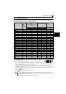
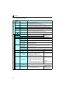
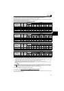
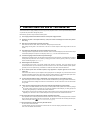
Three-phase 200V class (when input power supply is 220V)
Three-phase 400V class (when input power supply is 440V)
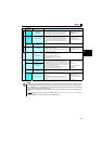
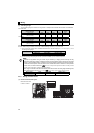
Single-phase 200V class (when input power supply is 220V)
Single-phase 100V class (when input power supply is 100V)
∗1 The cable size is that of the cable (HIV cable (600V class 2 vinyl-insulated cable) etc.) with continuous maximum permissible temperature of 75°C. Assumes
that the surrounding air temperature is 50°C or less and the wiring distance is 20m or less.
∗2 The recommended cable size is that of the cable (THHW cable) with continuous maximum permissible temperature of 75°C. Assumes that the surrounding
air temperature is 40°C or less and the wiring distance is 20m or less. (Selection example for use mainly in the United States.)
∗3 The recommended cable size is that of the cable (PVC cable) with continuous maximum permissible temperature of 70°C. Assumes that the surrounding air
temperature is 40°C or less and the wiring distance is 20m or less. (Selection example for use mainly in Europe.)
∗4 The terminal screw size indicates the terminal size for R/L1, S/L2, T/L3, U, V, W, PR, P/+, N/-, P1 and a screw for earthing (grounding).
Screw size for earthing (grounding) the FR-D720-15K is indicated in parentheses.
For single-phase power input, the terminal screw size indicates the size of terminal screw for R/L1, S/L2, U, V, W, PR, P/+, N/-, P1 and a screw for earthing
(grounding).
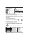
The line voltage drop can be calculated by the following formula:
Line voltage drop [V]=
Use a larger diameter cable when the wiring distance is long or when it is desired to decrease the voltage drop (torque
reduction) in the low speed range.
Applicable Inverter
Model
Terminal
Screw
Size ∗4
Tightening
Torque
N
·
m
Crimping
Terminal
Cable Size
HIV Cables, etc. (mm
2
) ∗1
AWG ∗2
PVC Cables, etc. (mm
2
) ∗3
R/L1
S/L2
T/L3
U, V, W
R/L1
S/L2
T/L3
U, V, W
Earthing
(grounding)
cable
R/L1
S/L2
T/L3
U, V, W
R/L1
S/L2
T/L3
U, V, W
Earthing
(grounding)
cable
FR-D720-0.1K to 0.75K M3.5 1.2 2-3.5 2-3.5 2 2 2 14 14 2.5 2.5 2.5
FR-D720-1.5K, 2.2K M4 1.5 2-4 2-4 2 2 2 14 14 2.5 2.5 2.5
FR-D720-3.7K M4 1.5 5.5-4 5.5-4 3.5 3.5 3.5 12 12 4 4 4
FR-D720-5.5K M5 2.5 5.5-5 5.5-5 5.5 5.5 5.5 10 10 6 6 6
FR-D720-7.5K M5 2.5 14-5 8-5 14 8 5.5 6 8 16 10 6
FR-D720-11K M5 2.5 14-5 14-5 14 14 14 6 6 16 16 16
FR-D720-15K M6 (M5) 4.4 22-6 22-6 22 22 14 4 4 25 25 16
Applicable Inverter
Model
Terminal
Screw
Size ∗4
Tightening
Torque
N
·
m
Crimping
Terminal
Cable Size
HIV Cables, etc. (mm
2
) ∗1
AWG ∗2
PVC Cables, etc. (mm
2
) ∗3
R/L1
S/L2
T/L3
U, V, W
R/L1
S/L2
T/L3
U, V, W
Earthing
(grounding)
cable
R/L1
S/L2
T/L3
U, V, W
R/L1
S/L2
T/L3
U, V, W
Earthing
(grounding)
cable
FR-D740-0.4K to 3.7K M4 1.5 2-4 2-4 2 2 2 14 14 2.5 2.5 2.5
FR-D740-5.5K M4 1.5 5.5-4 2-4 3.5 2 3.5 12 14 4 2.5 4
FR-D740-7.5K M4 1.5 5.5-4 5.5-4 3.5 3.5 3.5 12 12 4 4 4
FR-D740-11K M4 1.5 5.5-4 5.5-4 5.5 5.5 8 10 10 6 6 10
FR-D740-15K M5 2.5 8-5 8-5 8 8 8 8 8 10 10 10
Applicable Inverter
Model
Terminal
Screw
Size ∗4
Tightening
Torque
N
·
m
Crimping
Terminal
Cable Size
HIV Cables, etc. (mm
2
) ∗1
AWG ∗2
PVC Cables, etc. (mm
2
) ∗3
R/L1
S/L2
U, V, W
R/L1
S/L2
U, V, W
Earthing
(grounding)
cable
R/L1
S/L2
U, V, W
R/L1
S/L2
U, V, W
Earthing
(grounding)
cable
FR-D720S-0.1K to 0.75K M3.5 1.2 2-3.5 2-3.5 2 2 2 14 14 2.5 2.5 2.5
FR-D720S-1.5K M4 1.5 2-4 2-4 2 2 2 14 14 2.5 2.5 2.5
FR-D720S-2.2K M4 1.5 5.5-4 2-4 3.5 2 3.5 12 14 4 2.5 4
Applicable Inverter
Model
Terminal
Screw
Size ∗4
Tightening
Torque
N
·
m
Crimping
Terminal
Cable Size
HIV Cables, etc. (mm
2
) ∗1
AWG ∗2
PVC Cables, etc. (mm
2
) ∗3
R/L1
S/L2
U, V, W
R/L1
S/L2
U, V, W
Earthing
(grounding)
cable
R/L1
S/L2
U, V, W
R/L1
S/L2
U, V, W
Earthing
(grounding)
cable
FR-D710W-0.1K to 0.4K M3.5 1.2 2-3.5 2-3.5 2 2 2 14 14 2.5 2.5 2.5
FR-D710W-0.75K M4 1.5 5.5-4 2-4 3.5 2 2 12 14 4 2.5 2.5
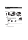
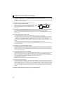
NOTE
y
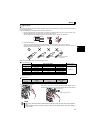
Tighten the terminal screw to the specified torque. A screw that has been tightened too loosely can cause a short circuit or
malfunction. A screw that has been tightened too tightly can cause a short circuit or malfunction due to the unit breakage.
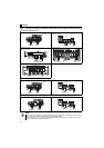
y Use crimping terminals with insulation sleeve to wire the power supply and motor.
3 × wire resistance[mΩ/m] × wiring distance[m] × current[A]
1000