


19
PRECAUTIONS FOR USE OF THE INVERTER
(12) Do not apply a voltage higher than the permissible voltage to the inverter I/O signal circuits.
Application of a voltage higher than the permissible voltage to the inverter I/O signal circuits or opposite polarity may
damage the I/O devices. Especially check the wiring to prevent the speed setting potentiometer from being connected
incorrectly to short terminals 10 and 5.
(14) If the machine must not be restarted when power is restored after a power failure, provide a magnetic contactor
in the inverter's input side and also make up a sequence which will not switch ON the start signal.
If the start signal (start switch) remains ON after a power failure, the inverter will automatically restart as soon as the
power is restored.
(15) Inverter input side magnetic contactor (MC)
On the inverter input side, connect a MC for the following purposes. (Refer to page 6 for selection.)
1)To release the inverter from the power supply when a fault occurs or when the drive is not functioning (e.g. emergency
stop operation). For example, MC avoids overheat or burnout of the brake resistor when heat capacity of the resistor is
insufficient or brake regenerative transistor is damaged with short while connecting an optional brake resistor.
2)To prevent any accident due to an automatic restart at restoration of power after an inverter stop made by a power
failure
3)To separate the inverter from the power supply to ensure safe maintenance and inspection work.
If using an MC for emergency stop during operation, select an MC regarding the inverter input side current as JEM1038-
AC-3 class rated current.
(16) Handling of inverter output side magnetic contactor
Switch the magnetic contactor between the inverter and motor only when both the inverter and motor are at a stop. When
the magnetic contactor is turned ON while the inverter is operating, overcurrent protection of the inverter and such will
activate. When MC is provided for switching to the commercial power supply, for example, switch it ON/OFF after the
inverter and motor have stopped.
(17) Countermeasures against inverter-generated EMI
If electromagnetic noise generated from the inverter causes frequency setting signal to fluctuate and motor rotation
speed to be unstable when changing motor speed with analog signal, the following countermeasures are effective.
y Do not run the signal cables and power cables (inverter I/O cables) in parallel with each other and do not bundle them.
y Run signal cables as far away as possible from power cables (inverter I/O cables).
y Use shield cables as signal cables.
y Install a ferrite core on the signal cable (Example: ZCAT3035-1330 TDK).
(18) Instructions for overload operation
When performing operation of frequent start/stop of the inverter, rise/fall in the temperature of the transistor element of
the inverter will repeat due to a repeated flow of large current, shortening the life from thermal fatigue. Since thermal
fatigue is related to the amount of current, the life can be increased by reducing current at locked condition, starting
current, etc. Decreasing current may increase the life. However, decreasing current will result in insufficient torque and
the inverter may not start. Therefore, choose the inverter which has enough allowance for current (up to 2 rank larger in
capacity).
(19) Make sure that the specifications and rating match the system requirements.
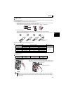
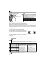
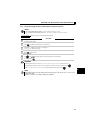
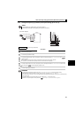
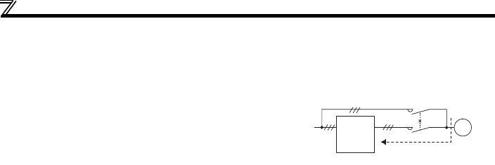
(13) Provide electrical and mechanical interlocks for MC1 and
MC2 which are used for bypass operation.
When the wiring is incorrect and if there is a bypass operation
circuit as shown right, the inverter will be damaged due to arcs
generated at the time of switch-over or chattering caused by a
sequence error.
Power
supply
Inverter
Undesirable current
MC2
MC1
Interloc
k
U
V
W
R/L1
S/L2
T/L3
IM