


A-2
(2) Wiring
(3) Trial run
(4) Usage
(5) Emergency stop
(6) Maintenance, inspection and parts replacement
(7) Disposal
zDo not install a power factor correction capacitor or surge
suppressor/capacitor type filter on the inverter output side.
These devices on the inverter output side may be
overheated or burn out.
zThe connection orientation of the output cables U, V, W to
the motor affects the rotation direction of the motor.
zBefore starting operation, each parameter must be
confirmed and adjusted. A failure to do so may cause some
machines to make unexpected motions.
zAny person must stay away from the equipment when the
retry function is set as it will restart suddenly after trip.
z
Since pressing key may not stop output depending on
the function setting status, separate circuit and switch that
make an emergency stop (power OFF, mechanical brake
operation for emergency stop, etc.) must be provided.
zOFF status of the start signal must be confirmed before
resetting the inverter fault. Resetting inverter alarm with the
start signal ON restarts the motor suddenly.
zThe inverter must be used for three-phase induction
motors.
Connection of any other electrical equipment to the inverter
output may damage the equipment.
zDo not modify the equipment.
z
Do not perform parts removal which is not instructed in this
manual. Doing so may lead to fault or damage of the product.
zThe electronic thermal relay function does not guarantee
protection of the motor from overheating. It is
recommended to install both an external thermal and PTC
thermistor for overheat protection.
zDo not use a magnetic contactor on the inverter input for
frequent starting/stopping of the inverter. Otherwise, the
life of the inverter decreases.
zThe effect of electromagnetic interference must be reduced
by using an EMC filter or by other means. Otherwise
nearby electronic equipment may be affected.
zAppropriate measures must be taken to suppress
harmonics. Otherwise power supply harmonics from the
inverter may heat/damage the power factor correction
capacitor and generator.
zWhen driving a 400V class motor by the inverter, the motor
must be an insulation-enhanced motor or measures must
be taken to suppress surge voltage. Surge voltage
attributable to the wiring constants may occur at the motor
terminals, deteriorating the insulation of the motor.
z
When parameter clear or all parameter clear is performed, the
required parameters must be set again before starting
operations because all parameters return to the initial value.
zThe inverter can be easily set for high-speed operation.
Before changing its setting, the performances of the motor
and machine must be fully examined.
zStop status cannot be hold by the inverter's brake function.
In addition to the inverter's brake function, a holding device
must be installed to ensure safety.
zBefore running an inverter which had been stored for a
long period, inspection and test operation must be
performed.
zStatic electricity in your body must be discharged before
you touch the product. Otherwise the product may be
damaged.
zIf you are installing the inverter to drive a three-phase
device while you are contracted for lighting and power
service, consult your electric power supplier.
CAUTION
CAUTION
WARNING
CAUTION
zA safety backup such as an emergency brake must be
provided to prevent hazardous condition to the machine
and equipment in case of inverter failure.
zWhen the breaker on the inverter input side trips, the wiring
must be checked for fault (short circuit), and internal parts
of the inverter for a damage, etc. The cause of the trip must
be identified and removed before turning ON the power of
the breaker.
zWhen any protective function is activated, appropriate
corrective action must be taken, and the inverter must be
reset before resuming operation.
zDo not carry out a megger (insulation resistance) test on
the control circuit of the inverter. It will cause a failure.
zThe inverter must be treated as industrial waste.
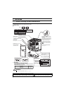
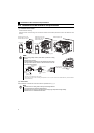
General instruction
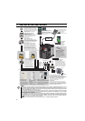
Many of the diagrams and drawings in this Instruction Manual
(Basic) show the inverter without a cover or partially open for
explanation. Never operate the inverter in this manner. The
cover must be always reinstalled and the instruction in this
Instruction Manual (Basic) must be followed when operating
the inverter.
<Abbreviation>
y PU: Operation panel and parameter unit (FR-PU04/FR-
PU07)
y Inverter: Mitsubishi inverter FR-D700 series
y FR-D700: Mitsubishi inverter FR-D700 series
y Pr.: Parameter number (Number assigned to function)
y PU operation: Operation using the PU (operation panel/FR-
PU04/FR-PU07)
y External operation: Operation using the control circuit
signals
y Combined operation: Operation using both the PU
(operation panel/FR-PU04/FR-PU07) and External operation
y Standard motor : SF-JR
y Constant torque motor: SF-HRCA
<Trademark>
y Company and product names herein are the trademarks
and registered trademarks of their respective owners.
<Mark>
REMARKS:Additional helpful contents and relations
with other functions are stated.
Note
: Contents requiring caution or cases when
set functions are not activated are stated.
POINT
: Useful contents and points are stated.
<Related document>
Refer to the Instruction Manual (Applied) for further
information on the following points.
y Removal and reinstallation of the cover
y Connection of stand-alone option unit
y EMC and leakage currents
y Detailed explanation on parameters
y Troubleshooting
y Check first when you have a trouble
y Inspection items (life diagnosis, cooling fan replacement)
y Measurement of main circuit voltages, currents and powers
y For customers who are replacing the conventional model
with this inverter
CAUTION
CAUTION
CAUTION