


36
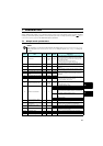
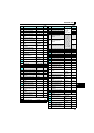
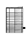
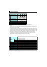
List of fault displays
8
Fault
Overcurrent trip during
acceleration
Overcurrent has occurred during acceleration.
y Set the acceleration time longer. (Shorten the downward
acceleration time in vertical lift application.)
y If "E.OC1" always appears at start, disconnect the motor once
and restart the inverter. If "E.OC1" still appears, the inverter
may be faulty. Contact your sales representative.
y Check the wiring for output short circuit and ground fault.
y When the rated motor frequency is 50Hz, set the Pr. 3 Base
frequency to 50Hz.
y Lower the stall prevention operation level.
y Activate the stall prevention operation and the fast-response
current limit operation. (Pr.156)
y For the operation with frequent regenerative driving, set the
base voltage (rated motor voltage, etc.) in Pr. 19 Base frequency
voltage.
Overcurrent trip during
constant speed
Overcurrent has occurred during constant speed
operation.
y Keep the load stable.
y Check the wiring to avoid output short circuit or ground fault.
y Lower the stall prevention operation level.
y Activate the stall prevention operation and the fast-response
current limit operation. (Pr.156)
Overcurrent trip during
deceleration or stop
Overcurrent has occurred during deceleration or
at a stop.
y Set the deceleration time longer.
y Check the wiring to avoid output short circuit or ground fault.
y Check if the mechanical brake is set to be activated too early.
y Lower the stall prevention operation level.
y Activate the stall prevention operation and the fast-response
current limit operation. (Pr.156)
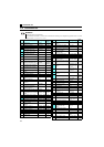
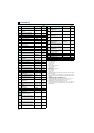
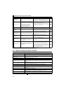
Regenerative
overvoltage trip during
acceleration
Overvoltage has occurred during acceleration.
y Set the acceleration time shorter.
y Use the regeneration avoidance function (Pr. 882, Pr. 883,
Pr. 885, Pr. 886).
y Set the Pr.22 Stall prevention operation level correctly.
Regenerative
overvoltage trip during
constant speed
Overvoltage has occurred during constant speed
operation.
y Keep the load stable.
y Use the regeneration avoidance function (Pr. 882, Pr. 883,
Pr. 885, Pr. 886).
y Use the brake resistor, brake unit or power regeneration
common converter (FR-CV) as required.
y Set the Pr.22 Stall prevention operation level correctly.
Regenerative
overvoltage trip during
deceleration or stop
Overvoltage has occurred during deceleration or
at a stop.
y Set the deceleration time longer. (Set the deceleration time
which matches the moment of inertia of the load)
y
Make the brake cycle longer.
y Use the regeneration avoidance function (Pr. 882, Pr. 883,
Pr. 885, Pr. 886).
y Use the brake resistor, brake unit or power regeneration
common converter (FR-CV) as required.
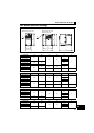
Inverter overload trip
(electronic thermal O/L
relay function) ∗1
The electronic thermal relay function for inverter
element protection has been activated.
y Set the acceleration/deceleration time longer.
y Adjust the Pr. 0 Torque boost setting.
y Set the Pr. 14 Load pattern selection setting according to the load
pattern of the using machine.
y Reduce the load.
y Set the surrounding air temperature to within the specifications.
Motor overload trip
(electronic thermal O/L
relay function)
∗1
The electronic thermal relay function for motor
protection has been activated.
y Reduce the load.
y For a constant-torque motor, set the constant-torque motor in
Pr. 71 Applied motor.
y Set the stall prevention operation level accordingly.
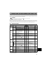
Heatsink overheat The heatsink has overheated.
y Set the surrounding air temperature to within the specifications.
y Clean the heatsink.
y Replace the cooling fan.
Input phase loss
∗3
One of the three phases on the inverter input side
has been lost. It may also appear if phase-to-
phase voltage of the three-phase power input
has become largely unbalanced.
y Wire the cables properly.
y Repair a break portion in the cable.
y Check the Pr. 872 Input phase loss protection selection setting.
y Set Pr. 872 = "0" (without input phase loss protection) when
three-phase input voltage is largely unbalanced.
Stall prevention stop
The output frequency has dropped to 1Hz as a
result of deceleration due to the excess motor
load.
Reduce the load. (Check the Pr. 22 Stall prevention operation level
setting.)
Brake transistor alarm
detection
A fault has occurred in the brake circuit, such as
a brake transistor breakage. (In this case, the
inverter must be powered off immediately.)
Replace the inverter.
Output side earth
(ground) fault
overcurrent at start ∗2
An earth (ground) fault has occurred on the
inverter's output side (detected only at a start).
Remedy the ground fault portion.
Output phase loss
One of the three phases (U, V, W) on the
inverter's output side (load side) has been lost
during inverter operation.
y Wire the cables properly.
y If the motor capacity is smaller than the inverter capacity,
choose the inverter and motor capacities that match.
External thermal relay
operation ∗2
The external thermal relay connected to the OH
signal has been activated.
y Reduce the load and operate less frequently.
y Even if the relay contacts are reset automatically, the inverter
will not restart unless it is reset.
PTC thermistor operation
∗2
Resistance of the PTC thermistor connected
between the terminal 2 and terminal 10 has
reached the Pr. 561 PTC thermistor protection level
setting value or higher.
Reduce the load.
Function Name Description Corrective action Display