


6
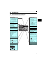
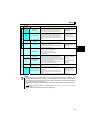
Peripheral devices
2
2.1 Peripheral devices
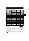
Check the inverter model of the inverter you purchased. Appropriate peripheral devices must be selected according to the capacity.
Refer to the following list and prepare appropriate peripheral devices.
∗1 ySelect a MCCB according to the power supply capacity.
yInstall one MCCB per inverter.
∗2 For the use in the United States or Canada, select an UL and cUL certified fuse with Class T fuse equivalent cut-off
speed or faster with the appropriate rating for branch circuit protection. Alternatively, select a UL489 molded case circuit breaker (MCCB). (Refer to page 46)
∗3 Magnetic contactor is selected based on the AC-1 class. The electrical durability of magnetic contactor is 500,000 times. When the magnetic contactor is
used for emergency stop during motor driving, the electrical durability is 25 times.
If using an MC for emergency stop during motor driving, select an MC regarding the inverter input side current as JEM1038-AC-3 class rated current. When
using an MC on the inverter output side for commercial-power supply operation switching using a general purpose motor, select an MC regarding the motor
rated current as JEM1038-AC-3 class rated current.
∗5 The power factor may be slightly lower.
∗6 Single-phase 100V power input model is not compatible with DC reactor.
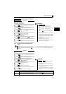
Inverter Model
Motor
Output
(kW)
Moulded Case Circuit Breaker
(MCCB) ∗1
or Earth Leakage Circuit Breaker
(ELB) ∗2
(NF or NV type)
Magnetic Contactor (MC)
∗3
Reactor
Reactor connection Reactor connection
FR-HAL FR-HEL
without with without with
Three-Phase 200V
FR-D720-0.1K 0.1 5A 5A S-N10 S-N10 0.4K ∗5 0.4K ∗5
FR-D720-0.2K 0.2 5A 5A S-N10 S-N10 0.4K ∗5 0.4K ∗5
FR-D720-0.4K 0.4 5A 5A S-N10 S-N10 0.4K 0.4K
FR-D720-0.75K 0.75 10A 5A S-N10 S-N10 0.75K 0.75K
FR-D720-1.5K 1.5 15A 10A S-N10 S-N10 1.5K 1.5K
FR-D720-2.2K 2.2 20A 15A S-N10 S-N10 2.2K 2.2K
FR-D720-3.7K 3.7 30A 30A S-N20, S-N21 S-N10 3.7K 3.7K
FR-D720-5.5K 5.5 50A 40A S-N20, S-N21 S-N20, S-N21 5.5K 5.5K
FR-D720-7.5K 7.5 60A 50A S-N25 S-N20, S-N21 7.5K 7.5K
FR-D720-11K 11 75A 75A S-N35 S-N35 11K 11K
FR-D720-15K 15 125A 100A S-N50 S-N50 15K 15K
Three-Phase 400V
FR-D740-0.4K 0.4 5A 5A S-N10 S-N10 H0.4K H0.4K
FR-D740-0.75K 0.75 5A 5A S-N10 S-N10 H0.75K H0.75K
FR-D740-1.5K 1.5 10A 10A S-N10 S-N10 H1.5K H1.5K
FR-D740-2.2K 2.2 15A 10A S-N10 S-N10 H2.2K H2.2K
FR-D740-3.7K 3.7 20A 15A S-N10 S-N10 H3.7K H3.7K
FR-D740-5.5K 5.5 30A 20A S-N20, S-N21 S-N11, S-N12 H5.5K H5.5K
FR-D740-7.5K 7.5 30A 30A S-N20, S-N21 S-N20, S-N21 H7.5K H7.5K
FR-D740-11K 11 50A 40A S-N20, S-N21 S-N20, S-N21 H11K H11K
FR-D740-15K 15 60A 50A S-N25 S-N20, S-N21 H15K H15K
Single-Phase 200V
FR-D720S-0.1K 0.1 5A 5A S-N10 S-N10 0.4K ∗5 0.4K ∗5
FR-D720S-0.2K 0.2 5A 5A S-N10 S-N10 0.4K ∗5 0.4K ∗5
FR-D720S-0.4K 0.4 10A 10A S-N10 S-N10 0.75K ∗5 0.75K ∗5
FR-D720S-0.75K 0.75 15A 10A S-N10 S-N10 1.5K ∗5 1.5K ∗5
FR-D720S-1.5K 1.5 20A 20A S-N10 S-N10 2.2K ∗5 2.2K ∗5
FR-D720S-2.2K 2.2 40A 30A S-N20, S-N21 S-N10 3.7K ∗5 3.7K ∗5
Single-Phase 100V
FR-D710W-0.1K 0.1 10A 5A S-N10 S-N10
0.75K
∗4
,
∗5
— ∗6
FR-D710W-0.2K 0.2 10A 10A S-N10 S-N10 1.5K ∗4, ∗5 — ∗6
FR-D710W-0.4K 0.4 15A 15A S-N10 S-N10 2.2K ∗4, ∗5 — ∗6
FR-D710W-0.75K 0.75 30A 20A S-N10 S-N10 3.7K ∗4, ∗5 — ∗6
∗4 When connecting a single-phase 100V power input model to a power transformer (50kVA or more), install an AC reactor (FR-HAL) so that the performance
is more reliable. ( Refer to Chapter 3 of the Instruction Manual (Applied))
NOTE
y When the inverter capacity is larger than the motor capacity, select an MCCB and a magnetic contactor according to the inverter model,
and cable and reactor according to the motor output.
y When the breaker on the inverter input side trips, check for the wiring fault (short circuit), damage to internal parts of the inverter, etc.
Identify the cause of the trip, then remove the cause and power ON the breaker.
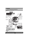
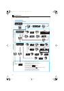
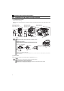
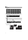
MCCB INV
MCCB INV
IM
IM