


9
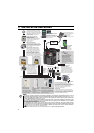
Wiring
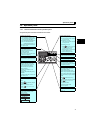
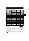
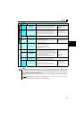
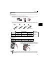
2.3.2 Terminal specifications
Type
Terminal
Symbol
Terminal Name Terminal Specification
Main circuit terminal
R/L1, S/L2,
T/L3
∗
AC power input
Connect to the commercial power supply.
Do not connect anything to these terminals when using the high power factor converter (FR-
HC) or power regeneration common converter (FR-CV).
* When using single-phase power input, terminals are R/L1 and S/L2.
U, V, W Inverter output
Connect a three-phase squirrel-cage motor.
P/+, PR Brake resistor connection
Connect a brake resistor (FR-ABR, MRS type, MYS type) across terminals P/+ and PR.
(The brake resistor can not be connected to the 0.1K and 0.2K.)
P/+, N/- Brake unit connection
Connect the brake unit (FR-BU2), power regeneration common converter (FR-CV) or high
power factor converter (FR-HC).
P/+, P1 ∗ DC reactor connection
Remove the jumper across terminals P/+ and P1 and connect a DC reactor. (Single-phase
100V power input model is not compatible with the DC reactor.)
* Terminal P1 is not available for single-phase 100V power input model.
Earth (Ground)
For earthing (grounding) the inverter chassis. Must be earthed (grounded).
Control circuit terminal/Input signal
Contact input
STF Forward rotation start
Turn ON the STF signal to start forward rotation and turn it OFF
to stop.
When the STF and STR
signals are turned ON
simultaneously, the stop
command is given.
STR Reverse rotation start
Turn ON the STR signal to start reverse rotation and turn it
OFF to stop.
RH, RM, RL Multi-speed selection
Multi-speed can be selected according to the combination of RH, RM and RL signals.
SD
Contact input common
(sink) (initial setting)
Common terminal for contact input terminal (sink logic) and terminal FM.
External transistor
common (source)
Connect this terminal to the power supply common terminal of a transistor output (open
collector output) device, such as a programmable controller, in the source logic to avoid
malfunction by undesirable current.
24VDC power supply
common
Common output terminal for 24VDC 0.1A power supply (PC terminal).
Isolated from terminals 5 and SE.
PC
External transistor
common (sink)
(initial setting)
Connect this terminal to the power supply common terminal of a transistor output (open
collector output) device, such as a programmable controller, in the sink logic to avoid
malfunction by undesirable current.
Contact input common
(source)
Common terminal for contact input terminal (source logic).
24VDC power supply
Can be used as 24VDC 0.1A power supply.
Frequency setting
10
Frequency setting power
supply
Used as power supply when connecting potentiometer for
frequency setting (speed setting) from outside of the inverter.
5VDC
permissible load current
10mA
2
Frequency setting
(voltage)
Inputting 0 to 5VDC (or 0 to 10V) provides the maximum output
frequency at 5V (10V) and makes input and output
proportional. Use Pr. 73 to switch between input 0 to 5VDC
input (initial setting) and 0 to 10VDC.
Input resistance10kΩ ± 1kΩ
Permissible maximum voltage
20VDC
4
Frequency setting
(current)
Inputting 4 to 20mADC (or 0 to 5V, 0 to 10V) provides the
maximum output frequency at 20mA and makes input and
output proportional. This input signal is valid only when the AU
signal is ON (terminal 2 input is invalid). To use terminal 4
(initial setting is current input), set "4" in any of Pr.178 to Pr.182
(input terminal function selection) to assign the function, and turn
ON AU signal.
Use Pr. 267 to switch among input 4 to 20mA (initial setting), 0
to 5VDC and 0 to 10VDC. Set the voltage/current input switch
in the "V" position to select voltage input (0 to 5V/0 to 10V).
Current input:
Input resistance 249Ω ± 5Ω
Maximum permissible current
30mA
Voltage input:
Input resistance10kΩ ± 1kΩ
Permissible maximum voltage
20VDC
5
Frequency setting
common
Frequency setting signal (terminal 2, 4) common terminal. Do not earth (ground).
Thermistor
10
2
PTC thermistor input
For connecting PTC thermistor output.
When PTC thermistor protection is valid (Pr. 561 ≠ "9999"),
terminal 2 is not available for frequency setting.
Adaptive PTC thermistor
specification
Heat detection resistance :
500Ω to 30kΩ (Set by Pr. 561)