


16
Wiring
2
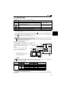
2.3.6 Safety stop function
(1) Description of the function
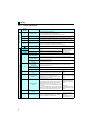
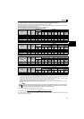
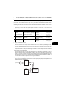
The terminals related to the safety stop function are shown below.
∗1 In the initial status, terminal S1 and S2 are shorted with terminal SC by shortening wire. Remove the shortening wire and connect the safety relay module
when using the safety stop function.
∗2
In the initial setting, safety monitor output signal (SAFE signal) is assigned to terminal SO. The function can be assigned to other terminals by setting "80 (positive
logic) or 180 (negative logic)" to any of
Pr. 190, Pr. 192 or Pr. 197 (Output terminal function selection)
. (
Refer to Chapter 4 of the Instruction Manual (Applied)
)
∗3 In the initial setting, inverter running (RUN signal) is assigned to terminal RUN. Set "81" to Pr. 190 RUN terminal function selection to assign SAFE2 signal. The
function can be assigned to other terminals by setting "81 (positive logic) or 181 (negative logic)" to any of Pr. 190, Pr. 192 or Pr. 197 (Output terminal function
selection). ( Refer to Chapter 4 of the Instruction Manual (Applied))
∗4 At an internal safety circuit fault, E.SAF or E.CPU is displayed on the operation panel.
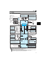
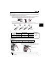
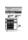
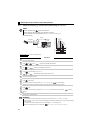
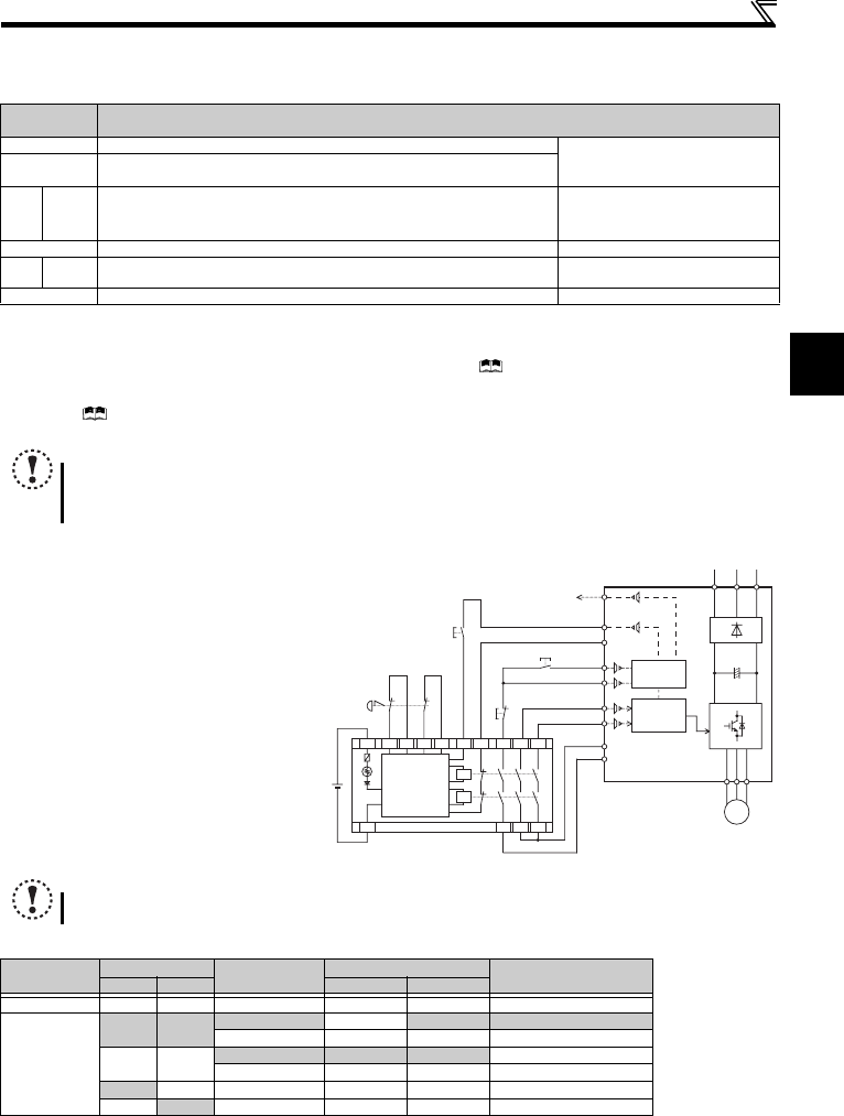
(2) Wiring connection diagram
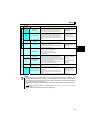
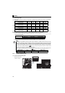
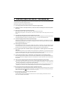
(3) Safety stop function operation
" N/A " denotes a condition where circuit fault does not apply.
∗1 At an internal safety circuit fault, E.SAF or E.CPU is displayed on the operation panel.
∗2 SA is displayed on the operation panel when both the S1 and S2 signals are in the open state without any internal safety circuit fault (E.SAF, E.CPU).
∗3 ON: Transistor used for an open collector output is conducted.
OFF: Transistor used for an open collector output is not conducted.
For more details, refer to the Safety stop function instruction manual (BCN-A211508-000). (Please contact your sales representative
for the manual.)
Terminal
Symbol
Description
S1 ∗1 For input of safety stop channel 1. Between S1 and SC / S2 and SC
Open: In safety stop mode.
Short: Other than safety stop mode.
S2
∗1 For input of safety stop channel 2.
SO
∗2
SAFE
signal
For output of safety stop condition.
The signal is output when inverter output is shut off due to the safety stop
function.
OFF: Drive enabled, or drive stop (at
an internal safety circuit fault
∗4)
ON: Drive stop (no internal safety
circuit fault
∗4)
SC Common terminal for S1,S2,SO signals. (SC is connected terminal SD internally.) —
RUN
∗3
SAFE2
signal
Outputs when an alarm or failure is detected
Outputs when there is no internal safety circuit fault
∗4
OFF: Internal safety circuit fault ∗4
ON: No internal safety circuit fault ∗4
SE Common terminal for open collector outputs (terminal RUN) —
NOTE
y Use SAFE signal for the purpose to monitor safety stop status. SAFE signal cannot be used as safety stop input
signal to other devices (other than the safety relay module.)
y SAFE2 signal can only be used to output an alarm or to prevent restart of an inverter. The signal cannot be used as
safety stop input signal to other devices.
NOTE
y Changing the terminal assignment using Pr. 190, Pr. 192, and Pr. 197 (output terminal function selection) may affect the
other functions. Set parameters after confirming the function of each terminal.
Input power
Input signal
Internal safety
circuit∗1
Output signal
Operation state
S1-SC S2-SC SAFE∗3 SAFE2∗3
OF F ----- ----- ----- O FF OFF Output sh utoff (Safe sta te)
ON
Short Short
No failure OFF ON Drive enabled
Detected OFF OFF Output shutoff (Safe state)
Open Open
No failure∗2 ON ON Output shutoff (Safe state)
Detected OFF OFF Output shutoff (Safe state)
Short Open N/A OFF OFF Output shutoff (Safe state)
Open
Short N/A OFF OFF Output shutoff (Safe state)
S2
S1
SC
Inverter
START/RESET
+24V
Emergency
stop button
QS90SR2SN-Q
K1
X0 X1
COM0
COM1
24G
Internal
Safety
Circuit
XS0
XS1
Z10
Z00
Z20
Z11 Z01 Z21
K2
DC24V
RUN (SAFE2)
R/L1
S/L2
T/L3
U V W
MITSUBISHI MELSEC Safety relay module
IM
SE
STF
STR(STOP)
STF
STOP
SD
Output
shutoff
circuit
I/O control
SO (SAFE)
monitor
To prevent restart at fault occurrence,
connect terminals RUN (SAFE2 signal) and
SE to terminals XS0 and XS1, which are the
feedback input terminals of the safety relay
module.
By setting Pr.190 RUN terminal function
selection = "81 (SAFE2 signal)", terminal
RUN is turned OFF at fault occurrence.
∗1 Output signals differ by the setting of Pr. 190, Pr.
192 and Pr. 197 (Output terminal function selection).
∗2 Input signals differ by the setting of Pr. 178 to Pr.
182 (Input terminal function selection).
y
Pr. 178
= "60 (initial value)"
y
Pr. 179
= "25"
y
Pr. 190
= "81"
y
Pr. 197
= "80 (initial value)"
∗2
∗2
∗1
∗1