


35
List of fault displays
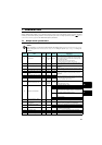
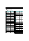
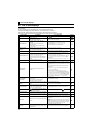
8.2 List of fault displays
When a fault occurs in the inverter, the inverter trips and the PU display automatically changes to one of the following fault or
alarm indications.
The error message shows an operational error. The inverter output is not shut off.
Warnings are messages given before faults occur. The inverter output is not shut off.
Alarms warn the operator of failures with output signals. The inverter output is not shut off.
When faults occur, the protective functions are activated to the inverter trip and output the fault signals.
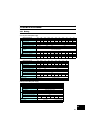
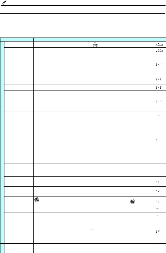
Function Name Description Corrective action Display
Error message
Operation panel lock
Operation has been attempted during the
operation panel lock.
Press for 2s to release lock.
Password locked
Reading/writing of a password-restricted
parameter has been attempted.
Enter the password in Pr. 297 Password lock/unlock to unlock the
password function before operating.
Write disable error
y Parameter setting has been attempted
although parameter writing is set to be
disabled.
y Overlapping range has been set for the
frequency jump.
y PU and the inverter cannot make normal
communication.
y Check the setting of Pr. 77 Parameter write selection
y Check the settings of Pr. 31 to Pr. 36 (frequency jump).
y Check the connection of PU and the inverter.
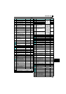
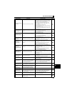
Write error during
operation
Parameter writing has been attempted while a
value other than "2" is set in Pr. 77Parameter write
selection and the STF (STR) is ON.
y Set "2" in Pr. 77 Parameter write selection.
y After stopping the operation, set parameters.
Calibration error
Analog input bias and gain calibration values
have been set too close.
Check the settings of calibration parameters C3, C4, C6 and C7
(calibration functions).
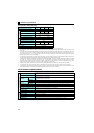
Mode designation error
y Parameter setting has been attempted in the
External or NET operation mode when Pr. 77
Parameter write selection is not "2."
y Parameter writing has been attempted when
the command source is not at the operation
panel.
y After setting the operation mode to the "PU operation mode,"
set parameters.
y Set "2" in Pr. 77 Parameter write selection
y Disconnect the parameter unit (FR-PU04/FR-PU07), then set
Pr. 551 PU mode operation command source selection = "9999
(initial setting)."
y Set Pr. 551 PU mode operation command source selection = "4."
Inverter reset
The reset signal (RES signal) is ON.
(Inverter output is shutoff.)
y Turn OFF the reset command
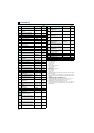
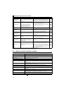
Warning
Stall prevention
(overcurrent)
The overcurrent stall prevention has been
activated.
y Increase or decrease the Pr. 0 Torque boost setting by 1% and
check the motor status.
y Set a larger value in Pr. 7 Acceleration time and Pr. 8 Deceleration
time.
y Reduce the load weight. Try General-purpose magnetic flux
vector control.
y Adjust the Pr. 13 Starting frequency setting. Change the Pr. 14
Load pattern selection setting.
y Set the stall prevention operation current in Pr. 22 Stall
prevention operation level. (The acceleration/deceleration time
may change.) Increase the stall prevention operation level with
Pr. 22 Stall prevention operation level, or disable stall prevention
with Pr. 156 Stall prevention operation selection. (Operation at OL
occurrence can be selected using Pr. 156 Stall prevention
operation selection.)
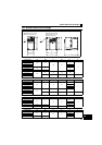
Stall prevention
(overvoltage)
The overvoltage stall prevention function has
been activated.
(This warning is also output during the
regeneration avoidance operation.)
Set the deceleration time longer.
Regenerative brake pre-
alarm ∗2
The regenerative brake duty has reached 85% of
the Pr. 70 Special regenerative brake duty setting or
higher.
y Set the deceleration time longer.
y Check that the Pr. 30 Regenerative function selection and Pr. 70
Special regenerative brake duty settings.
Electronic thermal relay
function pre-alarm
The cumulative value of the electronic thermal
O/L relay has reached 85% of the Pr. 9 Electronic
thermal O/L relay setting or higher.
y Reduce the load and frequency of operation.
y Set an appropriate value in Pr. 9 Electronic thermal O/L relay.
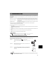
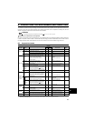
PU stop
on the operation panel has been pressed
during the External operation.
Turn the start signal OFF and release with .
Maintenance signal
output ∗2
The cumulative energization time has exceeded
the maintenance output timer set value.
Setting "0" in Pr. 503 Maintenance timer erases the signal.
Undervoltage
The voltage at the main circuit power has been
lowered.
Investigate the devices on the power supply line such as the
power supply itself.
Safety stop
Safety stop function activating (Outputs are being
shut off.)
y When not using the safety stop function, short across terminals
S1 and SC and across S2 and SC with shorting wire for the
inverter to run.
y
If is indicated when across S1 and SC and across S2 and
SC are both shorted while using the safety stop function (drive
enabled), internal failure might be the cause. Check the wiring
of terminals S1, S2 and SC and contact your sales
representative if the wiring has no fault.
Alarm
Fan alarm
The cooling fan is at a standstill although it is
required to be operated. The cooling fan speed
has decelerated.
Check for fan failure. Please contact your sales representative.