


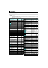
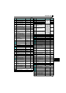
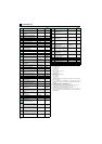

27
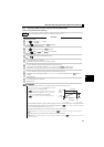
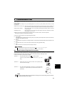
Start and stop using terminals (External operation)
5.2.3 Setting the frequency by analog input (voltage input/current input)
POINT
y Switch ON the STF(STR) signal to give a start command.
y Use the potentiometer (frequency setting potentiometer) (voltage input) or 4-to-20mA input (current input) to
give a frequency command.
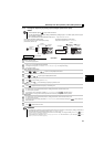
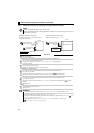
[Connection example for voltage input] [Connection example for current input]
(The inverter supplies 5V power to the frequency setting
potentiometer. (terminal 10))
Assign the AU signal in one of Pr. 178 to Pr. 182.
Operation example Operate at 60Hz.
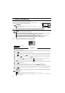
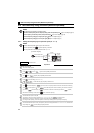
Operation
1.
Screen at power-ON
The monitor display appears.
2.
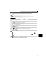
Assignment of the AU signal (current input) (Refer to the step 3 for voltage input.)
Set Pr. 160 to "0" to activate extended parameters.
To assign the AU signal, set "4" in one of Pr. 178 to Pr. 182. (Refer to page 4 to change the setting.)
Turn ON the AU signal.
3.
Start
Turn the start switch (STF or STR) ON.
[RUN] flickers fast because the frequency command is not given.
4.
Acceleration Æ constant speed
For voltage input, turn the potentiometer (frequency setting potentiometer) clockwise slowly to full.
For current input, input 20mA.
The frequency value on the display increases in Pr. 7 Acceleration time, and " " (60.00Hz) appears.
[RUN] indicator is lit during forward rotation operation and flickers slowly during reverse rotation operation.
5.
Deceleration
For voltage input, turn the potentiometer (frequency setting potentiometer) counterclockwise slowly to full.
For current input, input 4mA.
The frequency value on the display decreases in
Pr. 8 Deceleration time
, and the motor stops rotating with " " (0.00Hz)
displayed.
[RUN] flickers fast.
6.
Stop
Turn the start switch (STF or STR) OFF.
[RUN] turns OFF.
REMARKS
y To always select the External operation mode, set Pr. 79 Operation mode selection = "2 (External operation mode)".
y For voltage input, the frequency (maximum potentiometer setting) at the full right turn of the (frequency setting) potentiometer is
60Hz in the initial setting. (To change the setting, use Pr.125.) (Refer to page 28.)
y For current input, the frequency at 20mA input is 60Hz in the initial setting. (To change the setting, use Pr. 126.) ( Refer to
Chapter 4 of the Instruction Manual (Applied.))
y To input 10VDC to the terminal 2, set Pr.73 Analog input selection = "0". The initial value is "1 (0 to 5V input)".
( Refer to Chapter 4 of the Instruction Manual (Applied).)
Frequency setting
potentiometer
Inverter
5
10
2
Forward rotation start
Reverse rotation start
STF
STR
SD
Inverter
5(-)
4(+)
SD
AU signal (terminal RH)
AU signal
Forward rotation start
Reverse rotation start
STF
STR
Current signal
source
(4 to 20mADC)