


8
Wiring
2
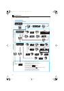
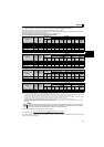
2.3 Wiring
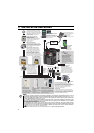
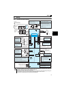
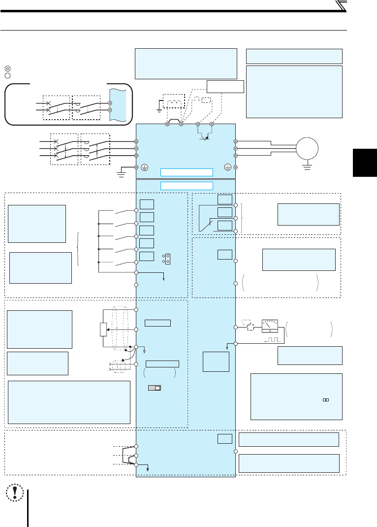
2.3.1 Terminal connection diagram
NOTE
y To prevent a malfunction caused by noise, separate the signal cables more than 10cm from the power cables. Also
separate the main circuit wire of the input side and the output side.
y After wiring, wire offcuts must not be left in the inverter.
Wire offcuts can cause an alarm, failure or malfunction. Always keep the inverter clean. When drilling mounting holes
in an enclosure etc., take care not to allow chips and other foreign matter to enter the inverter.
y The output of the single-phase power input model is three-phase 200V.
Earth
(Ground)
Motor
IM
Earth (Ground)
Three-phase
AC power
supply
MCCB MC
R/L1
P1 P/+
PR
N/-
S/L2
T/L3
U
V
W
Earth
(Ground)
*7 Brake resistor (FR-ABR, MRS type, MYS
type)
Install a thermal relay to prevent an
overheat and burnout of the brake resistor.
Always install a thermal relay when using
a brake resistor whose capacity is 11K or
higher.
(The brake resistor can not be connected
to the 0.1K and 0.2K.)
*8 It is not necessary when
calibrating the indicator
from the operation panel.
*9 Operation and parameter setting can be
done from the parameter unit (FR-
PU07) and the enclosure surface
operation panel (FR-PA07).
(Use the option cable (FR-CB2 ).)
RS-485 communication can be utilized
from a personal computer and other
devices.
Forward
rotation start
Reverse
rotation start
Middle
speed
High
speed
Low
speed
Control input signals (No voltage input allowed)
24VDC power supply
(Common for external power supply transistor)
Contact input common
STR
STF
RH
RM
RL
SD
PC
Relay output
Running
Open collector output
Open collector output common
Sink/source common
RUN
SE
A
B
C
Frequency setting signals (Analog)
2 0 to 5VDC
10(+5V)
2
3
1
4 4 to 20mADC
Frequency
setting
potentiometer
1/2W1kΩ
Terminal 4
input
(Current
input)
(+)
(-)
5(Analog common)
*4 It is recommended to
use 2W1kΩ when the
frequency setting signal
is changed frequently.
*4
*2 When using terminals PC-
SD as a 24VDC power
supply, take care not to
short across terminals
PC and SD.
PU
connector
*
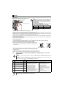
1. DC reactor (FR-HEL)
When connecting a DC reactor, remove the
jumper across P1 and P/+.
Single-phase 100V power input model is not
compatible with DC reactor.
Control circuit terminal
Main circuit terminal
Sink logic
Jumper
*1
*7
*6
*2
*3
*5
The function of these
terminals can be
changed to the reset
signal, etc. with the input
terminal assignment
(Pr. 178 to Pr. 182)
.
Multi-speed selection
Terminal functions vary by
Pr. 190 RUN terminal function
selection
Terminal functions vary
by Pr. 192 A,B,C terminal
function selection
SINK
SOURCE
VI
*5
0 to 5VDC
(0 to 10VDC)
0 to 10VDC
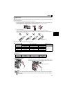
*5 Terminal input specifications can be changed by analog
input specifications switchover (Pr. 267). Set the
voltage/current input switch in the "V" position to select
voltage input (0 to 5V/0 to10V) and "I" (initial value) to
select current input (4 to 20mA).
To use terminal 4 (initial setting is current input), set "4"
in any of Pr.178 to Pr.182 (input terminal function
selection) to assign the function, and turn ON AU signal.
Voltage/current
input switch
Main circuit
Control circuit
R
Relay output
(Fault output)
Brake unit
(Option)
FM
SD
Indicator
(Frequency meter, etc.)
+
-
Moving-coil type
1mA full-scale
Calibration resistor
*8
*9
*3 Terminal input specifications
can be changed by analog
input specifications
switchover (Pr. 73).
Terminal 10 and terminal 2
are used as PTC input
terminal (Pr. 561).
Safe stop input (Channel 1)
Safe stop input (Channel 2)
Safe stop input common
Safety stop signal
S1
S2
SC
SO
Shorting
wire
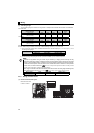
Single-phase
AC power
supply
MCCB MC
R/L1
S/L2
Single-phase power input
*6 Terminal P1 is not available for single-
phase 100V power input model.
*10 Common terminal of terminal SO is
terminal SC. (Connected to terminal SD
inside of the inverter.)
Safety monitor output *10
Terminal functions vary by Pr. 197 SO
terminal function selection