


33
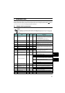
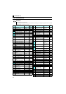
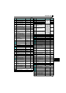
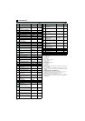
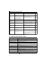
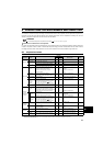
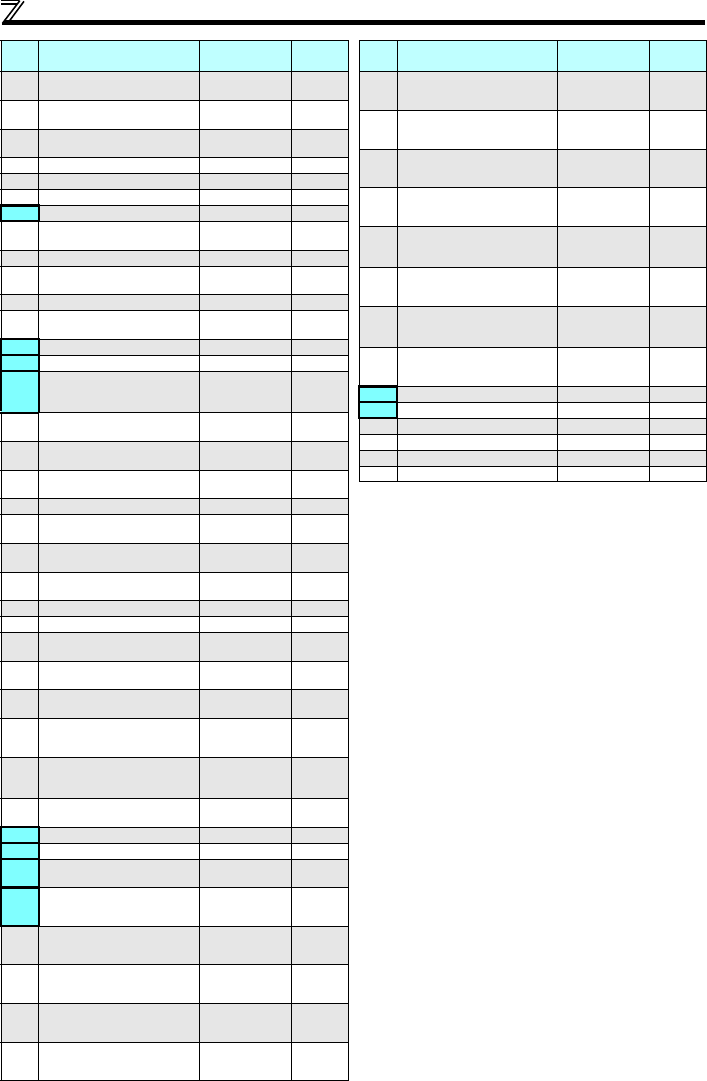
Parameter list
∗1 Differ according to capacities.
6%: 0.75K or lower
4%: 1.5K to 3.7K
3%: 5.5K, 7.5K
2%: 11K, 15K
∗2 Differ according to capacities.
5s: 3.7K or lower
10s: 5.5K, 7.5K
15s: 11K, 15K
∗3 Differ according to capacities.
6%: 0.1K, 0.2K
4%: 0.4K to 7.5K
2%: 11K, 15K
∗4 The initial value differs according to the voltage class. (100V class, 200V
class / 400V class)
∗5 Set this parameter when calibrating the operation panel built-in
potentiometer for the FR-E500 series operation panel (PA02) connected
with cable.
∗6 The setting value "60" is only available for Pr. 178.
∗7 The setting value "61" is only available for Pr. 179.
∗8 The setting value "93" and "193" are only available for Pr. 190 and Pr. 197.
∗9 The setting value "9999" is only available for Pr. 190 and Pr. 192.
∗10 Available only for the three-phase power input model.
∗11 The parameter number in parentheses is the one for use with the
operation panel (PA02) for the FR-E500 series or parameter unit (FR-
PU04/FR-PU07).
339
Communication speed
command source
0, 1, 2 0
340
Communication startup mode
selection
0, 1, 10 0
342
Communication EEPROM
write selection
0, 1 0
343 Communication error count — 0
450 Second applied motor 0, 1, 9999 9999
495 Remote output selection 0, 1, 10, 11 0
496 Remote output data 1 0 to 4095 0
502
Stop mode selection at
communication error
0, 1, 2 0
503 Maintenance timer 0 (1 to 9998) 0
504
Maintenance timer alarm
output set time
0 to 9998, 9999 9999
549 Protocol selection 0, 1 0
551
PU mode operation command
source selection
2, 4, 9999 9999
555 Current average time 0.1 to 1s 1s
556 Data output mask time 0 to 20s 0s
557
Current average value monitor
signal output reference current
0 to 500A
Rated
inverter
current
561 PTC thermistor protection level
0.5 to 30kΩ ,
9999
9999
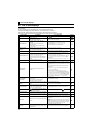
563
Energization time carrying-
over times
(0 to 65535) 0
564
Operating time carrying-over
times
(0 to 65535) 0
571 Holding time at a start 0 to 10s, 9999 9999
575
Output interruption detection
time
0 to 3600s, 9999 1s
576
Output interruption detection
level
0 to 400Hz 0Hz
577
Output interruption cancel
level
900 to 1100% 1000%
611 Acceleration time at a restart 0 to 3600s, 9999 9999
653 Speed smoothing control 0 to 200% 0
665
Regeneration avoidance
frequency gain
0 to 200% 100
872
∗10
Input phase loss protection
selection
0, 1 0
882
Regeneration avoidance
operation selection
0, 1, 2 0
883
Regeneration avoidance
operation level
300 to 800V
400VDC/
780VDC
∗4
885
Regeneration avoidance
compensation frequency limit
value
0 to 10Hz, 9999 6Hz
886
Regeneration avoidance
voltage gain
0 to 200% 100%
888 Free parameter 1 0 to 9999 9999
889 Free parameter 2 0 to 9999 9999
891
Cumulative power monitor digit
shifted times
0 to 4, 9999 9999
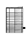
C0
(900)
∗11
FM terminal calibration — —
C2
(902)
∗11
Terminal 2 frequency setting
bias frequency
0 to 400Hz 0Hz
C3
(902)
∗11
Terminal 2 frequency setting
bias
0 to 300% 0%
125
(903)
∗11
Terminal 2 frequency setting
gain frequency
0 to 400Hz 60Hz
C4
(903)
∗11
Terminal 2 frequency setting
gain
0 to 300% 100%
Pr.
Name Setting Range
Initial
Value
C5
(904)
∗11
Terminal 4 frequency setting
bias frequency
0 to 400Hz 0Hz
C6
(904)
∗11
Terminal 4 frequency setting
bias
0 to 300% 20%
126
(905)
∗11
Terminal 4 frequency setting
gain frequency
0 to 400Hz 60Hz
C7
(905)
∗11
Terminal 4 frequency setting
gain
0 to 300% 100%
C22
(922)
∗5∗11
Frequency setting voltage bias
frequency (built-in
potentiometer)
0 to 400Hz 0
C23
(922)
∗5∗11
Frequency setting voltage bias
(built-in potentiometer)
0 to 300% 0
C24
(923)
∗5∗11
Frequency setting voltage gain
frequency (built-in
potentiometer)
0 to 400Hz 60Hz
C25
(923)
∗5∗11
Frequency setting voltage gain
(built-in potentiometer)
0 to 300% 100%
990 PU buzzer control 0, 1 1
991 PU contrast adjustment 0 to 63 58
Pr.CL Parameter clear 0, 1 0
ALLC All parameter clear 0, 1 0
Er.CL Fault history clear 0, 1 0
Pr.CH Initial value change list — —
Pr.
Name Setting Range
Initial
Value