


11
Wiring
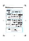
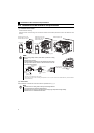
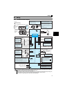
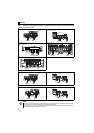
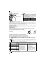
2.3.3 Terminal arrangement of the main circuit terminal, power supply and the motor wiring
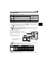
zThree-phase 200V/400V class
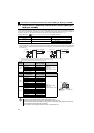
zSingle-phase 200V class
zSingle-phase 100V class
FR-D720-0.1K to 0.75K FR-D720-1.5K to 3.7K
FR-D740-0.4K to 3.7K
FR-D720-5.5K, 7.5K
FR-D740-5.5K, 7.5K
FR-D720-11K, 15K
FR-D740-11K, 15K
FR-D720S-0.1K to 0.75K FR-D720S-1.5K, 2.2K
FR-D710W-0.1K to 0.4K FR-D710W-0.75K
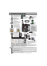
NOTE
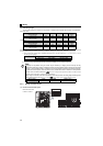
y Make sure the power cables are connected to the R/L1, S/L2, T/L3. (Phase need not be matched.) Never connect the
power cable to the U, V, W of the inverter. Doing so will damage the inverter.
y Connect the motor to U, V, W. Turning ON the forward rotation switch (signal) at this time rotates the motor
counterclockwise when viewed from the load shaft.
MotorPower supply
N/-
P/+ PR
IM
R/L1 S/L2 T/L3
Jumpe
r
Motor
Power supply
N/-
P/+
PR
IM
R/L1 S/L2 T/L3
Jumper
Power supply Motor
IM
Jumper
N/-
P/+ PR
R/L1S/L2 T/L3
N/-
P/+
PR
R/L1 S/L2 T/L3
Jumper
MotorPower supply
IM
Motor
Power supply
IM
N/-
P/+
PR
R/L1 S/L2 T/L3
Jumper
MotorPower supply
N/-
P/+ PR
IM
Jumpe
r
R/L1 S/L2
N/-
P/+
PR
R/L1 S/L2
MotorPower supply
IM
Jumper
MotorPower supply
N/-
P/+ PR
IM
R/L1 S/L2
N/-
P/+
PR
R/L1 S/L2
MotorPower supply
IM