


44
(2) Low Voltage Directive
We have self-confirmed our inverters as products compliant to the Low Voltage Directive (Conforming standard EN 61800-
5-1) and affix the CE marking on the inverters.
Outline of instructions
∗ Do not use an earth leakage circuit breaker as an electric shock protector without connecting the equipment to the earth.
Connect the equipment to the earth securely.
∗ Wire the earth (ground) terminal independently. (Do not connect two or more cables to one terminal.)
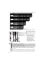
∗ Use the cable sizes on page 12 under the following conditions.
ySurrounding air temperature: 40°C maximum
If conditions are different from above, select appropriate wire according to EN60204 ANNEX C TABLE 5.
∗ Use a tinned (plating should not include zinc) crimping terminal to connect the earth cable. When tightening the screw,
be careful not to damage the threads.
For use as a product compliant with the Low Voltage Directive, use PVC cable on page 12.
∗ Use the moulded case circuit breaker and magnetic contactor which conform to the EN or IEC Standard.
∗ When using an earth leakage circuit breaker, use a residual current operated protective device (RCD) of type B (breaker
which can detect both AC and DC). If not, provide double or reinforced insulation between the inverter and other
equipment, or put a transformer between the main power supply and inverter.
∗ Use the inverter under the conditions of overvoltage category II (usable regardless of the earth (ground) condition of the
power supply), overvoltage category III (usable with the earthed-neutral system power supply, 400V class only) specified
in IEC664.
yTo use the inverter under the conditions of pollution degree 3, install it in the enclosure of IP54 or higher.
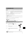
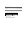
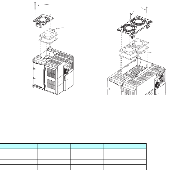
yTo use the inverter outside of an enclosure in the environment of pollution degree 2, fix a fan cover with fan cover fixing
screws enclosed.
Note, the protection structure of the Inverter units is considered to be an IP00.
∗ On the input and output of the inverter, use cables of the type and size set forth in EN60204 Appendix C.
∗ The operating capacity of the relay outputs (terminal symbols A, B, C) should be 30VDC, 0.3A. (Relay output has basic
isolation from the inverter internal circuit.)
∗ Control circuit terminals on page 8 are safely isolated from the main circuit.
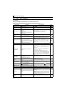
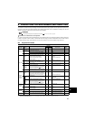
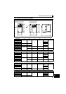
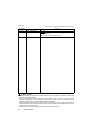
∗ Environment
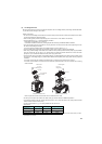
3.7K or lower
Example for FR-D740-1.5K
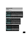
5.5K or higher
Example for FR-D740-7.5K
Running In Storage During Transportation
Surrounding air
temperature
-10°C to +50°C -20°C to +65°C -20°C to +65°C
Humidity 90% RH or less 90% RH or less 90% RH or less
Maximum Altitude 1000m 1000m 10000m
Details are given in the technical information "Low Voltage Directive Conformance Guide" (BCN-A21041-203). Please contact your sales
representative for the manual.
Fan connection
connector
Fan
Fan cover
Fan cover
fixing screw
Fan
Fan cover
Fan cover
fixing screws
Fan connection
connector