


10
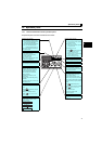
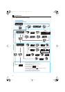
Wiring
2
* For more details, refer to the Safety stop function instruction manual (BCN-A211508-000). (Please contact your sales representative for the manual.)
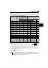
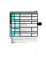
Control circuit terminal/Output signal
Relay
A, B, C
Relay output
(fault output)
1 changeover contact output indicates that the inverter
protective function has activated and the output stopped.
Fault: discontinuity across B-C (continuity across A-C),
Normal: continuity across B-C (discontinuity across A-C)
Contact capacity:230VAC
0.3A (power factor =0.4)
30VDC 0.3A
Open collector
RUN Inverter running
Switched Low when the inverter output frequency is equal to or
higher than the starting frequency (initial value 0.5Hz).
Switched High during stop or DC injection brake operation.
(Low is when the open collector output transistor is ON
(conducts). High is when the transistor is OFF (does not
conduct).)
Permissible load 24VDC
(maximum 27VDC) 0.1A
(a voltage drop is 3.4V
maximum when the signal is
ON)
SE
Open collector output
common
Common terminal of terminal RUN.
Pulse
FM For meter
Used to output a selected monitored item (such as Output
frequency) among several monitored items.
(Not output during inverter reset.)
The output signal is proportional to the magnitude of the
corresponding monitored item.
Permissible load current 1mA
1440 pulses/s at 60Hz
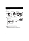
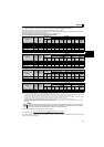
Communication
— PU connector
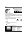
With the PU connector, communication can be established through RS-485.
yConforming standard: EIA-485 (RS-485)
yTransmission format: Multidrop link
yCommunication speed: 4800 to 38400bps
yOverall length: 500m
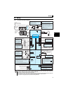
Safety stop function *
S1
Safety stop input
(Channel 1)
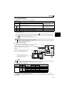
Terminals S1 and S2 are for safety stop input signals used with
the safety relay module. Terminals S1 and S2 are used
simultaneously (dual channel). Inverter output is shut off by
shortening/opening across terminals S1 and SC and across S2
and SC. In the initial status, terminals S1 and S2 are shorted
with terminal SC by shortening wire.
Remove the shortening wire and connect the safety relay
module when using the safety stop function.
Input resistance 4.7kΩ
Voltage when contacts are
open
21 to 26VDC
When contacts are short-
circuited
4 to 6mADC
S2
Safety stop input
(Channel 2)
SC
Safety stop input terminal
common
Common terminal for terminals S1, S2 and SO. Connected to terminal SD inside of the
inverter.
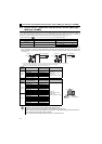
SO
Safety monitor output
(open collector output)
The signal indicates the status of safety stop input.
Low indicates safe state, and High indicates drive enabled or
fault detected.
(Low is when the open collector output transistor is ON
(conducts). High is when the transistor is OFF (does not
conduct).)
Permissible load 24VDC
(maximum 27VDC) 0.1A
(a voltage drop is 3.4V
maximum when the signal is
ON)
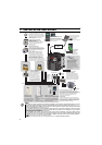
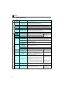
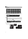
NOTE
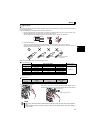
y To change the input specification for terminal 4, set Pr. 267 and the voltage/current input switch correctly, then input
the analog signal relevant to the setting. Applying a voltage with voltage/current input switch in "I" position (current
input is selected) or a current with switch in "V" position (voltage input is selected) could cause component damage
to the inverter or analog circuit of output devices.
y Connecting the power supply to the inverter output terminals (U, V, W) will damage the inverter. Do not perform such
wiring.
y indicates that terminal functions can be selected using Pr. 178 to Pr. 182, Pr. 190, Pr. 192, Pr. 197 (I/O terminal
function selection).
y The terminal names and functions shown here are the initial settings.
Type
Terminal
Symbol
Terminal Name Terminal Specification