


41
Common specifications
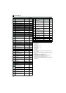
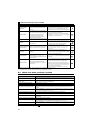
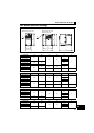
z Single-phase 100V power supply
∗1 The applicable motor capacity indicated is the maximum capacity applicable for use of the Mitsubishi 4-pole standard motor.
∗2 The rated output capacity assumes the following output voltages: 230V for three-phase 200V/single-phase 200V/single-phase 100V, and 440V for three-
phase 400V.
∗3 The % value of the overload current rating indicated is the ratio of the overload current to the inverter's rated output current. For repeated duty, allow time for
the inverter and motor to return to or below the temperatures under 100% load. If the automatic restart after instantaneous power failure function (Pr. 57) or
power failure stop function (Pr. 261) is set and power supply voltage is low while load becomes bigger, the bus voltage decreases to power failure detection
level and load of 100% or more may not be available.
∗4 The maximum output voltage does not exceed the power supply voltage. The maximum output voltage can be changed within the setting range. However,
the pulse voltage value of the inverter output side voltage remains unchanged at about that of the power supply.
∗5 The braking torque indicated is a short-duration average torque (which varies with motor loss) when the motor alone is decelerated from 60Hz in the shortest
time and is not a continuous regenerative torque. When the motor is decelerated from the frequency higher than the base frequency, the average
deceleration torque will reduce. Since the inverter does not contain a brake resistor, use the optional brake resistor when regenerative energy is large.
(Option brake resistor cannot be used for 0.1K and 0.2K.) A brake unit (FR-BU2) may also be used.
∗6 The power supply capacity varies with the value of the power supply side inverter impedance (including those of the input reactor and cables).
∗7 For single-phase 100V power input model, the maximum output voltage is twice the amount of the power supply voltage and cannot be exceeded.
∗8 In a single-phase 100V power input model, the output voltage may fall down when the load is heavy, and larger output current may flow compared to a three-
phase input model. Use the motor with less load so that the output current is within the rated motor current range.
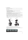
10.2 Common specifications
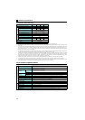
∗1 When using the inverters at the surrounding air temperature of 40°C or less, the inverters can be installed closely attached (0cm clearance).
∗2 Temperatures applicable for a short time, e.g. in transit.
Model FR-D710W-K 0.1 0.2 0.4 0.75
Applicable motor capacity (kW)∗1 0.1 0.2 0.4 0.75
Output
Rated capacity (kVA)∗2 0.30.61.01.7
Rated current (A) 0.8 1.4 2.5 4.2
Overload current rating∗3
150% 60s, 200% 0.5s
(inverse-time characteristics)
Rated voltage Three-phase 200 to 230V∗7, ∗8
Regenerative braking torque∗5 150% 100%
Power supply
Rated input AC voltage/frequency Single-phase 100 to 115V 50Hz/60Hz
Permissible AC voltage fluctuation 90 to 132V 50Hz/60Hz
Permissible frequency fluctuation ±5%
Power supply capacity (kVA)∗6 0.50.91.52.5
Protective structure (JEM1030) Enclosed type (IP20)
Cooling system Self-cooling
Approximate mass (kg) 0.6 0.7 0.9 1.4
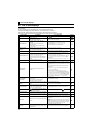
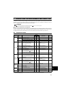
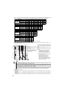
Control specifications
Control method
Soft-PWM control/high carrier frequency PWM control (V/F control, General-purpose magnetic flux vector control,
and Optimum excitation control are available)
Output frequency range 0.2 to 400Hz
Frequency setting
resolution
Analog input
0.06Hz/60Hz (terminal2, 4: 0 to 10V/10bit)
0.12Hz/60Hz (terminal2, 4: 0 to 5V/9bit)
0.06Hz/60Hz (terminal4: 0 to 20mA/10bit)
Digital input 0.01Hz
Frequency
accuracy
Analog input Within ±1% of the maximum output frequency (25°C ±10°C)
Digital input Within 0.01% of the set output frequency
Voltage/frequency characteristics Base frequency can be set from 0 to 400Hz. Constant-torque/variable torque pattern can be selected
Starting torque 150% or more (at 1Hz)...when General-purpose magnetic flux vector control and slip compensation is set
Torque boost Manual torque boost
Acceleration/deceleration time setting
0.1 to 3600s (acceleration and deceleration can be set individually),
Linear and S-pattern acceleration/deceleration modes are available.
DC injection brake
Operation frequency (0 to 120Hz), operation time (0 to 10s), and operation voltage (0 to 30%) can be changed
Stall prevention operation level
Operation current level (0 to 200%), and whether to use the function or not can be selected
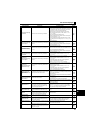
Environment
Surrounding air temperature
-10°C to +50°C maximum (non-freezing) ∗1
Ambient humidity
90%RH or less (non-condensing)
Storage temperature∗2
-20°C to +65°C
Atmosphere
Indoors (without corrosive gas, flammable gas, oil mist, dust and dirt etc.)
Altitude/vibration
Maximum 1000m above sea level, 5.9m/s
2
or less at 10 to 55Hz (directions of X, Y, Z axes)
2