


45
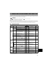
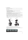
∗ Select a UL and cUL certified fuse with Class T fuse equivalent cut-off speed or faster with the appropriate rating for
branch circuit protection, or a UL489 molded case circuit breaker (MCCB) in accordance with the table below.
∗ Maximum allowable rating by US National Electrical Code. Exact size must be chosen for each installation.
∗ When using the electronic thermal relay function as motor overload protection, set the rated motor current in Pr. 9
Electronic thermal O/L relay.
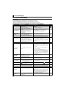
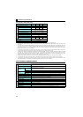
∗ Short circuit current ratings
y 100V class
Suitable For Use in A Circuit Capable of Delivering Not More Than 5 kA rms Symmetrical Amperes, 132V Maximum.
y 200V class
Suitable For Use in A Circuit Capable of Delivering Not More Than 5 kA rms Symmetrical Amperes, 264V Maximum.
y 400V class
Suitable For Use in A Circuit Capable of Delivering Not More Than 5 kA rms Symmetrical Amperes, 528V Maximum.
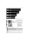
FR-D720-K 0.1 0.2 0.4 0.75 1.5 2.2 3.7 5.5 7.5 11 15
Rated fuse voltage(V) 240V or more
Fuse maximum
allowable rating
(A)∗
Without power factor
improving reactor
15 15 15 20 30 40 60 70 80 150 175
With power factor
improving reactor
15 15 15 20 20 30 50 60 70 125 150
Molded case circuit breaker (MCCB)
Maximum allowable rating (A)*
15 15 15 15 20 25 40 60 80 110 150
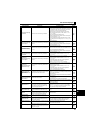
FR-D740-K 0.4 0.75 1.5 2.2 3.7 5.5 7.5 11 15
Rated fuse voltage(V) 480V or more
Fuse maximum
allowable rating
(A)∗
Without power factor
improving reactor
61015203040708090
With power factor
improving reactor
61010152535607090
Molded case circuit breaker (MCCB)
Maximum allowable rating (A)*
15 15 15 15 20 30 40 50 70
FR-D720S-K 0.1 0.2 0.4 0.75 1.5 2.2
Rated fuse voltage(V) 240V or more
Fuse maximum
allowable rating
(A)∗
Without power factor
improving reactor
15 20 20 30 40 60
With power factor
improving reactor
15 20 20 20 30 50
Molded case circuit breaker (MCCB)
Maximum allowable rating (A)*
15 15 15 20 25 40
FR-D710W-K 0.1 0.2 0.4 0.75
Rated fuse voltage(V) 115V or more
Fuse maximum
allowable rating
(A)∗
Without power factor
improving reactor
20 20 40 60
With power factor
improving reactor
20 20 30 50
Molded case circuit breaker (MCCB)
Maximum allowable rating (A)*
15 15 25 40
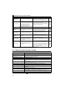
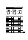
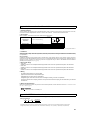
This function detects the overload (overheat)
of the motor, stops the operation of the
inverter's output transistor, and stops the
output.
(The operation characteristic is shown on the
left)
y When using the Mitsubishi constant-torque
motor
1) Set "1" or any of "13", "50", "53" in
Pr. 71
.
(This provides a 100% continuous torque
characteristic in the low-speed range.)
2) Set the rated current of the motor in Pr. 9.
∗1 When 50% of the inverter rated output current
(current value) is set in Pr. 9
∗2
The % value denotes the percentage to the
inverter rated output current. It is not the
percentage to the motor rated current.
∗3 When you set the electronic thermal relay
function dedicated to the Mitsubishi constant-
torque motor, this characteristic curve applies
to operation at 6Hz or higher.
NOTE
⋅ The internal thermal integrated value of the electronic thermal relay function is reset by inverter power reset and
reset signal input. Avoid unnecessary reset and power-OFF.
⋅ Install an external thermal relay (OCR) between the inverter and a motor when operating several motors by one
inverter, or when using a multi-pole motor or specialized motor. In this case, set 0A to the electronic thermal O/L relay
setting of the inverter. For the external thermal relay, determine the setting value in consideration of the current
indicated on the motor's rating plate and the line-to-line leakage current. Self-cooling ability of a motor is reduced at
low speed operation. Use a motor with a built-in thermal protector.
⋅ When the difference between the inverter and motor capacities is large and the setting is small, the protective
characteristics of the electronic thermal relay function will be deteriorated. In this case, use an external thermal relay.
⋅ A special motor cannot be protected by the electronic thermal relay function. Use the external thermal relay.
Operation range
Range on the right of characteristic curve
Non-operation range
Range on the left of characteristic curve
Range for
transistor
protection
Inverter output current(%) (% to the rated inverter current)
52.5%
105%
50
100
150
60
120
180
240
50
60
70
(min) unit display
in this range
Operation time (min)
Pr. 9 = 50% setting of inverter rating*1, 2
Pr. 9 = 100% setting of inverter rating*2
(s) unit display in this range
Operation time (s)
Characteristic when electronic thermal
relay function for motor protection is turned OFF
(when Pr. 9 setting is 0(A))
6Hz
20Hz
10Hz
6Hz
0.5Hz
30Hz or more
*3
30Hz
or more
*3
20Hz
10Hz
0.5Hz
200