


E6581090
I-6
9
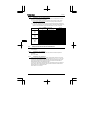
9.1.5 Compliance with Low voltage directive
Please carry out the below mentioned countermeasures for the Low Voltage Directive in case of
using VF-nC1 as components of your products.
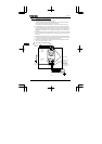
(1) Inverter should be installed in a panel. Pay attention to wiring openings, so that it should
prevent someone from touching live parts through the opening in case of maintenance.
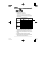
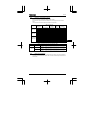
(2) No more than 1 cable should be connected to one earth terminal of the main terminal board.
In this case, other cables for ground should be grounded on the metal back plate and/or in the
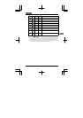
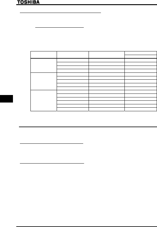
cubicle. The cross-sectional area of grounding cable shall be, in any case, not less than;
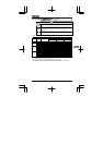
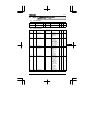
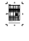
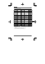
Table 3. Grounding cable
Wire size
Voltage class
Capacity of applicable
motor(kW)
Inverter model
Grounding cable
0.1 VFNC1S-1001P AWG 12 / 3.5 mm
2
0.2 VFNC1S-1002P AWG 12 / 3.5 mm
2
0.4 VFNC1S-1004P AWG 12 / 3.5 mm
2
Single-phase
100V
class
0.75 VFNC1S-1007P AWG 12 / 3.5 mm
2
0.2 VFNC1S-2002P(L) AWG 12 / 3.5 mm
2
0.4 VFNC1S-2004P(L) AWG 12 / 3.5 mm
2
0.75 VFNC1S-2007P(L) AWG 12 / 3.5 mm
2
1.5 VFNC1S-2015P(L) AWG 12 / 3.5 mm
2
Single-phase
200V
class
2.2 VFNC1S-2022P(L) AWG 10 / 5.5 mm
2
0.1 VFNC1-2001P AWG 12 / 3.5 mm
2
0.2 VFNC1-2002P AWG 12 / 3.5 mm
2
0.4 VFNC1-2004P AWG 12 / 3.5 mm
2
0.75 VFNC1-2007P AWG 12 / 3.5 mm
2
1.5 VFNC1-2015P AWG 12 / 3.5 mm
2
Three-phase
200V
class
2.2 VFNC1-2022P AWG 12 / 3.5 mm
2
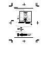
(3) MCCB or fuse should be connected to the input side of the EMI filter.
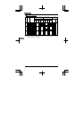
9.2 Compliance with UL Standard and CSA Standard
The VF-nC1 models, that conform to the UL Standard and CSA Standard have the UL/CSA mark
on the nameplate.
9.2.1 Compliance with Installation
The VF-nC1 inverter must be installed in a panel, and used within the ambient temperature
specification.
See 1.4.4 for details.
9.2.2 Compliance with Connection
Use the UL conformed cables (Rating 75℃ or more, Use the copper conductors only.) with the
ring terminal at wiring to the inverter input/ output terminals (R/L1, S/L2, T/L3, U/T1, V/T2, W/T3).
For instruction in the United States, Integral solid state short circuit protection does not provide
branch circuit protection. Branch circuit protection must be provided in accordance with the
National Electrical Code and any additional local codes.
For instruction in the Canada, Integral solid state short circuit protection does not provide branch
circuit protection. Branch circuit protection must be provided in accordance with the Canadian
Electrical Code and any additional local codes.
See the table in 10.1 for wire size.