


E6581090
E-12
5
☆SS3 (preset speed 3) and SS4 (preset speed 4) are not assigned to any terminals at the factory.
Before use, therefore, assign SS3 and SS4 to reserved terminals, using the input terminal
function selection parameter. In the above example, these functions are assigned to the R and
VI/S3 terminals.
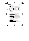
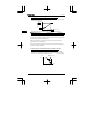
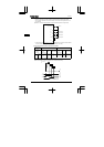
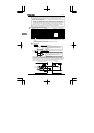
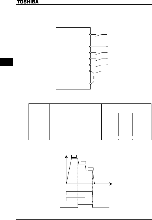
[Example of a connection diagram] (When the input terminals are placed in sink logic mode)
F (Forward run)
CC
S2
R
S1
Forward
Preset speed 1
Preset speed 4
Preset speed 3
Preset speed 2
P15
VI/S3
*1 :When using the VI/S3 terminal as a contact input terminal, be sure to insert a resistor* between
the P15 and VI/S3 terminals. (* Recommended resistance: 4.7kΩ-1/4W)
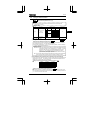
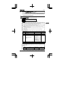
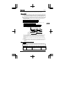
3) Using other speed commands with preset speed command
Command mode
selection
EOQF
0 : Terminal board
1 : Operation panel
Frequency
setting mode
selection
HOQF
0 : Terminal
board
(Analog signal)
1 : Operation
panel
2 : Potentiometer
0 : Terminal
board
(Analog signal)
1 : Operation
panel
2 : Potentiometer
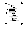
EnteredPreset speed command Valid Note)
Preset
speed
command
Not
entered
Analog signal
Valid
Operation
panel
Command
Valid
Potentiometer
Valid
Analog signal
Valid
Operation
panel
Command
Valid
Potentiometer
Valid
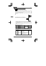
Note)The preset speed command is always given priority when other speed commands are input at
the same time.
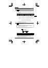
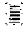
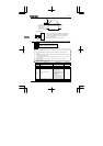
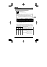
Below is an example of 3-step speed operation with standard default setting.
F-CC
S1(SS1)-CC
S2(SS2)-CC
ON
OFF
ON
OFF
ON
OFF
UT
UT
UT
O
utput frequency
[
Hz]
Time
[s]
0
Example of 3-step speed operation
*1
(The inverter doesn’t accept preset speed command.)