E6581090
N-1
14
14. Inspection and maintenance
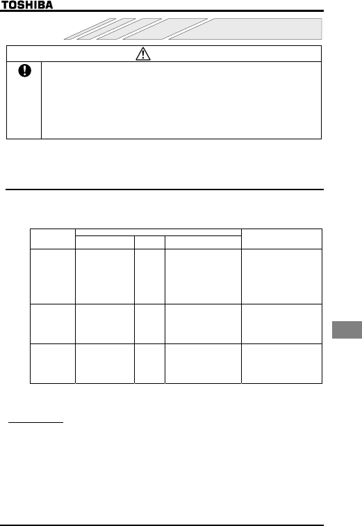
Warning
Mandatory
• The equipment must be inspected every day.
If the equipment is not inspected and maintained, errors and malfunctions may not be
discovered which could lead to accidents.
• Before inspection, perform the following steps.
①Shut off all input power to the inverter.
②Wait for at least 15 minutes and check that the charge lamp is no longer lit.
③Use a tester that can measure DC voltages (800V DC or more), and check that the
voltage to the DC main circuits (across PA-PC) does not exceed 45V.
Performing an inspection without carrying out these steps first could lead to electric shock.
Be sure to inspect the inverter regularly and periodically to prevent it from breaking down because
of the environment of use, such as temperature, humidity, dust and vibration, or deterioration of its
components with aging.
14.1 Regular inspection
Since electronic parts are susceptible to heat, install the inverter in a cool, well-ventilated and
dust-free place. This is essential for increasing the service life.
The purpose of regular inspections is to maintain the correct environment of use and to find any
sign of failure or malfunction by comparing current operation data with past operation records.
Inspection procedure
Subject of
inspection
Inspection item
Inspection
cycle
Inspection method
Criteria for judgment
1) Dust, temperature
and gas
Occasionally
1) Visual check, check by
means of a
thermometer, smell
check
1) Improve the environment
if it is found to be
unfavorable.
2) Drops of water or
other liquid
Occasionally
2) Visual check 2) Check for any trace of
water condensation.
1. Indoor
environment
3) Room
temperature
Occasionally
3) Check by means of a
thermometer
3) Max. temperature: 40°C
(50°C inside the cabinet)
2. Units and
components
1) Vibration and
noise
Occasionally
Tactile check of the cabinet
If something unusual is found,
open the door and check the
transformer, reactors,
contactors, relays, cooling fan,
etc., inside. If necessary, stop
the operation.
1) Load current
Occasionally
Moving-iron type AC
ammeter
2) Voltage (*)
Occasionally
Rectifier type AC voltmeter
3. Operation
data
(output side)
3) Temperature
Occasionally
Thermometer
To be within the rated
current, voltage and
temperature.
No significant difference from
data collected in a normal
state.
*) The voltage measured may slightly vary from voltmeter to voltmeter. When measuring the
voltage, always take readings from the same circuit tester or voltmeter.
■Check points
1. Something unusual in the installation environment
2. Something unusual in the cooling system
3. Unusual vibration or noise
4. Overheating or discoloration
5. Unusual odor
6. Unusual motor vibration, noise or overheating


