E6581090
F-5
6
• Function
This parameter is used to switch between sink logic (negative common) and source logic
(positive common).
3) Sink logic/source logic input
Switching between sink logic and source logic (input terminal logic) is possible.
6.2.4 Jog run
• Function
The VF-nC1 inverter is capable of jog operation if its input terminal selection function is so set.
Jog run refers to jogging or inching a motor. Input of a jog run signal causes the VF-nC1
inverter to produce a jog run signal (fixed at 5Hz) for 0.1 seconds (fixed), regardless of the
specified acceleration time. Cutting off a jog run signal causes the motor to coast to a stop.
■The motor continues to run in jog mode as long as both the jog run signal and the operation signal
are put out. To enable the jog run function, you need to assign the jog run function (4) to an
unassigned input terminal.
For the VF-nC1 inverter, all settings for jog run are fixed, as shown below.
Jogging frequency 5Hz
Jogging stop pattern Coast stop
Acceleration time 0.1 sec.
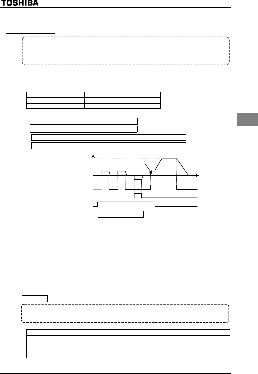
<Examples of jog run> (When the jog run function is assigned to the S1 terminal: H=4)
S1-CC (JOG) ON + F-CC ON: Forward jog run
S1-CC (JOG) ON + F-CC ON: Reverse jog run
( Normal operation frequency signal input + F-CC ON: Forward run )
( Normal operation frequency signal input + R-CC ON: Reverse run )
F-CC
R-CC
S1 (JOG)-CC
Normal operation
frequency setting
signal input
O
utput frequency [Hz]
Forward
Reverse
Forward
Forward
0
Set frequency
• The jog run terminals (S1-CC) are enabled when the operation frequency is below 5Hz. They
do not function when the operation frequency is higher than the jog run frequency (5Hz).
• The motor continues to run in jog mode while the jog run terminals (S1-CC) are electrically
connected.
• Jog run has priority, and it continues even if any other operation command is entered during
operation.
Note:During jog run, the VF-nC1 inverter may produce an Low-speed detection signal (LOW) signal
but not Designated frequency reach signal (RCH) signal, and therefore PI control is not
performed.
6.2.5 Switching between control logics
H
: Sink/Source selection
■Parameter setting
Title Function Adjustment range Default setting
H Sink/Source selection
Adjustable within a range of 0 to 200
0: Sink
100: Source
Others: Invalid
0
*The value is changed according to the set-up parameter condition. (VFNC1 (S)-□□□□P□-W type)
0 (sink) for VFNC1 (S)-□□□□P□ type.


