


E6581090
J-1
10
10. Peripheral devices
Warning
Prohibited
• If you take the power supply from an outlet, do not over the outlet’s rated current.
That could emit the outlet and may result in an ignition.
Mandatory
• When using wiring materials and their optional devices for the inverter, they must
be installed in a cabinet.
Failure to do so can lead to risk of electric shock and can result in death or
serious injury.
Be Grounded
• Connect earth cables securely. Failure to do so can lead to risk of electric
shock or fire in case of a failure, short-circuit or leak current.
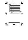
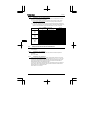
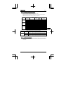
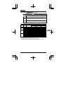
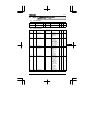
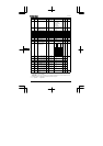
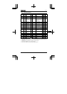
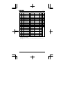
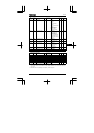
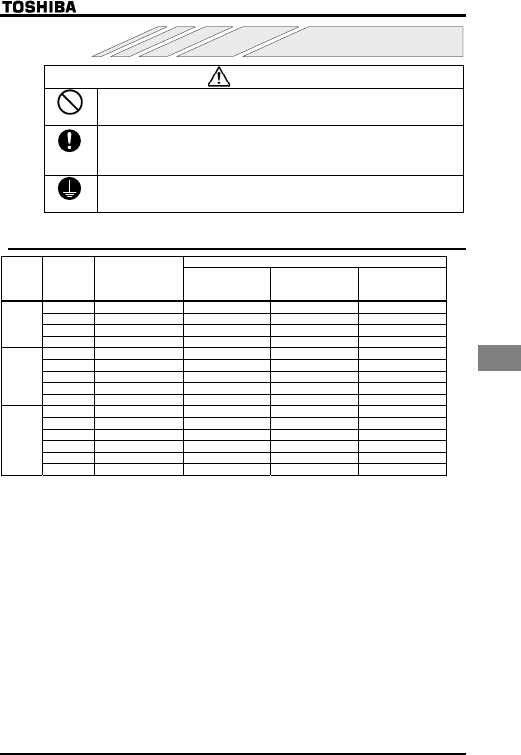
10.1 Selection of wiring materials and devices
Wire size
Voltage
class
Capacity of
applicable
motor
(kW)
Inverter model
Main circuit
(See Note 1.)
DC reactor
(optional)
Grounding cable
0.1 VFNC1S-1001P AWG 14 / 2.0 mm
2
- AWG 12 / 3.5 mm
2
0.2 VFNC1S-1002P AWG 14 / 2.0 mm
2
- AWG 12 / 3.5 mm
2
0.4 VFNC1S-1004P AWG 14 / 2.0 mm
2
- AWG 12 / 3.5 mm
2
Single-ph
ase 100V
class
0.75 VFNC1S-1007P AWG 14 / 3.5 mm
2
- AWG 12 / 3.5 mm
2
0.2 VFNC1S-2002P(L) AWG 14 / 2.0 mm
2
AWG 16 / 1.25 mm
2
AWG 12 / 3.5 mm
2
0.4 VFNC1S-2004P(L) AWG 14 / 2.0 mm
2
AWG 16 / 1.25 mm
2
AWG 12 / 3.5 mm
2
0.75 VFNC1S-2007P(L) AWG 14 / 2.0 mm
2
AWG 14 / 2.0 mm
2
AWG 12 / 3.5 mm
2
1.5 VFNC1S-2015P(L) AWG 10 / 3.5 mm
2
AWG 14 / 2.0 mm
2
AWG 12 / 3.5 mm
2
Single-ph
ase 200V
class
2.2 VFNC1S-2022P(L) AWG 10 / 5.5 mm
2
AWG 14 / 2.0 mm
2
AWG 10 / 5.5 mm
2
0.1 VFNC1-2001P AWG 14 / 2.0 mm
2
AWG 16 / 1.25 mm
2
AWG 12 / 3.5 mm
2
0.2 VFNC1-2002P AWG 14 / 2.0 mm
2
AWG 16 / 1.25 mm
2
AWG 12 / 3.5 mm
2
0.4 VFNC1-2004P AWG 14 / 2.0 mm
2
AWG 16 / 1.25 mm
2
AWG 12 / 3.5 mm
2
0.75 VFNC1-2007P AWG 14 / 2.0 mm
2
AWG 14 / 2.0 mm
2
AWG 12 / 3.5 mm
2
1.5 VFNC1-2015P AWG 10 / 2.0 mm
2
AWG 14 / 2.0 mm
2
AWG 12 / 3.5 mm
2
Three-ph
ase 200V
class
2.2 VFNC1-2022P AWG 10 / 2.0 mm
2
AWG 14 / 2.0 mm
2
AWG 12 / 3.5 mm
2
Note 1: Sizes of the wires connected to the input terminals R, S and T and the output terminals U, V and W
when the length of each wire does not exceed 30m.
Note 2: For the control circuit, use shielded wires 0.75 mm
2
or more in diameter.
Note 3: For grounding, use a cable with a size equal to or larger than the above.
Note 4: When using a crimp terminal, cover its caulked part with a tube or use an insulated terminal.