


E6581090
B-5
2
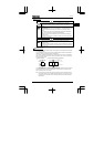
Main circuit
R/L1
S/L2
T/L3
P0 PA PC
DC reactor
(DCL: option)
U/T1
V/T2
W/T3
IM
VF-nC1
FLC
FLB
FLA
P5
VI/S3
*
2
*
3
CC
F
R
S1
S2
P15
FM/OUT
*
2
CC
+
-
Meter
Connector for
optional devices
Forward
Preset speed 2
Reverse
Preset speed 1
Common
Fault output signal
External potentiometer
(3-10k
Ω
)
or input voltage signal
(0-10Vdc)
Current signal
4-20mAdc
Frequency meter
(Ammeter)
Control circuit
MCCB
*1
Ry
*5
*4
1-phase series
Power
supply
R/L1
S/L2
1-phase series do not have T/L3 terminal.
MCCB
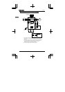
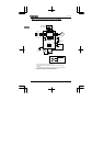
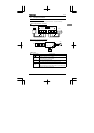
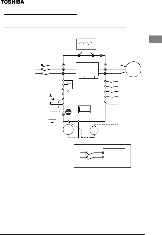
2.2.2 Standard connection diagram (2)
(2) Source <common: P15>
■When using V1/S3 terminal as an analog input terminal (H : or )
*1:Only European model has a built-in noise filter.
*2: The terminal can be switched between FM/OUT and VI/S3 by changing a
parameter.
*3: The terminal can also be used as an input terminal by changing a parameter.
*4: European models are not provided with PO terminal.
*5: 1-phase 100V models cannot be used with DC reactors.