


2 Installing Your System
16 Installing the Control Unit
Quick Reference Guide
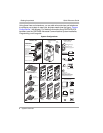
Wall-Mounting a 5-Slot Carrier and Modules
Install the 5-slot carrier within 5 feet (1.5 meters) of a properly grounded wall
outlet (not controlled by a switch) and the network interface jacks. When you
mount the carrier on the wall, leave at least 1 foot (0.3 meter) of clearance at the
top and sides and 2 feet (0.6 meter) at the front and bottom to ensure proper
ventilation.
Follow these steps to wall-mount the 5-slot carrier and modules:
1 Using the enclosed template, mark the screw locations on the wall. If you
are mounting the carrier on plywood, start four #12 screws supplied with the
carrier, leaving the screw heads extending approximately 1/4 inch (0.64 cm)
from the wall. If you are mounting on drywall, use wall anchors, which must
be purchased separately.
2 Before installing any modules, make sure the clear, plastic protector has
been removed from the connector area on the rear of each module. To
remove the protector, grasp the tabs on the ends of the protector and lift.
3 Insert the PARTNER ACS processor module in the center slot of the carrier.
4 In the other slots, from left to right, first install the T1 module (if used) or
1600 DSL module (if used), then the 012E, 308EC, or 206 modules,
followed by the 400 or 200 modules and/or a PARTNER Messaging or
PARTNER MAIL VS module. Align the module carefully in the appropriate
slot. For proper engagement of the connectors, the module must be
inserted straight into the carrier. Once the module is properly seated, firmly
push the center of the module until the connectors on the module lock into
place. A slight click indicates the connectors are engaged.
The location of each module within the carrier is important; place the
modules as instructed in the following procedure.