


Input / Output 4-5MN1903
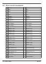
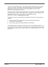
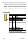
4.3.1 Analog inputs - X6
Location Breakout module, connector X6
Pin Name MintMT keyword / description
1 AGND Analog ground
2 AIN0+
A
I
N
0
3 AIN0-
A
IN0
4 AIN1+
A
I
N
1
5 AIN1-
A
IN1
6 Shield Shield connection
7 AGND Analog ground
8 AIN2+
A
I
N
2
9 AIN2-
A
IN2
10 AIN3+
A
I
N
3
11 AIN3-
A
IN3
12 Shield Shield connection
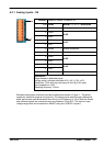
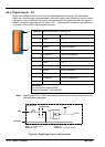
Description
Single ended or differential inputs
Voltage range: software selectable 0-5V, ±5V, 0-10V, ±10V
Resolution: 12-bit with sign (accuracy ±4.9mV @ ±10V input)
Input impedance: >5kΩ
Sampling frequency: 2.5kHz
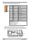
Shielded twisted pairs should be used and connected as shown in Figure 1. The shield
connection should be made at one end only. The analog inputs pass through a differential
buffer and second order Butterworth filter with a cut-off frequency of 1kHz. Both the filtered
and unfiltered signals are converted using a multiplexed 12-bit ADC. This has four input
voltage ranges that can be selected in MintMT using the ADCMODE keyword.
1
12