


Contents i
MN1903
Contents
1 General Information 1-1.................................
2 Introduction 2-1........................................
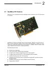
2.1 NextMove PCI features 2-1..................................
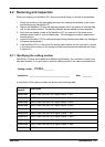
2.2 Receiving and inspection 2-3................................
2.2.1 Identifying the catalog number 2-3....................................
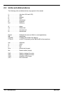
2.3 Units and abbreviations 2-4..................................
3 Basic Installation 3-1....................................
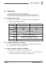
3.1 Introduction 3-1............................................
3.1.1 Hardware requirements 3-1.........................................
3.1.2 Tools and miscellaneous hardware 3-1................................
3.1.3 Other information needed for installation 3-1...........................
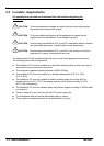
3.2 Location requirements 3-2...................................
3.3 Installation 3-3.............................................
3.3.1 Installing the NextMove PCI card 3-3.................................
3.3.2 NextMove PCI Expansion card and CAN Bracket board 3-3..............
4 Input / Output 4-1......................................
4.1 Outline 4-1................................................
4.2 100-pin edge connector 4-1..................................
4.2.1 100-pin connector pin assignment 4-2.................................
4.3 Analog I/O 4-4.............................................
4.3.1 Analog inputs - X6 4-5..............................................
4.3.2 Analog outputs (Drive Demand/Command) - X7 4-7.....................
4.4 Digital I/O 4-8..............................................
4.4.1 Digital inputs - X1 4-10..............................................
4.4.2 Digital inputs - X2 4-11..............................................
4.4.3 Digital inputs - X3 4-12..............................................
4.4.4 Digital outputs - X4 4-13.............................................
4.4.5 Digital outputs - X5 4-14.............................................
4.5 Other I/O 4-15..............................................
4.5.1 Encoder interfaces - X12, X13, X14, X15, X16 4-15......................
4.5.2 Encoder input frequency 4-16........................................
4.5.3 Power - X9 4-17....................................................
4.5.4 Relay and CAN power - X8 4-18......................................
4.5.5 Stepper drive outputs - X10, X11 4-19..................................