


4-22 Input / Output MN1903
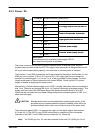
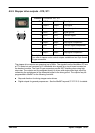
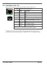
4.6.2 CAN2 (Baldor CAN) - X18
Baldor CAN connections are made using the breakout module connector X18.
Location
Breakout module, connector X18
Pin Name Description
1 - (NC)
2 - (NC)
3 - (NC)
4 CAN2 0V G round/earth reference for CAN signal
5 CAN2 V+ CAN remote node power V+ (12-24V)
6 - (NC)
7 CAN2+ CAN channel 2 positive
8 CAN2- CAN channel 2 negative
Description
Baldor proprietary CAN interface using a RJ45 connector.
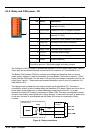
If NextMove PCI is at the end of the Baldor CAN network a termination resistor must be
connected by fitting the termination jumper J7, labelled “BC Term”, on the breakout module.
1 8