


Input / Output 4-25MN1903
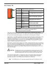
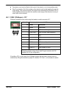
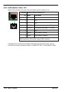
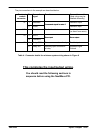
The pin connections in the example are described below:
Breakout
module
connector
Pin Name of
signal
Function Connection on drive
(Note: drive may be
labelled dif ferently)
X7 1 Demand0
C
o
m
m
a
n
d
s
i
g
n
a
l
f
o
r
a
x
i
s
0
Demand+ input
2 AGND
C
omman
d
s
i
gna
l
f
or a
x
i
s
0
Demand- input
X12 - Encoder Position feedback E ncoder out
(or direct from motor)
X1 2 DIN12
E
r
r
o
r
i
n
p
u
t
E
r
r
o
r
o
u
t
p
u
t
12 Common2
E
rror
i
npu
t
E
rror ou
t
pu
t
X8 7 Relay COM Common connection of relay Enable input
6 Relay NO Normally open connection
of relay
Amplifier/Digital
Ground
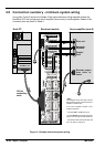
Table 4 - Connector details for minimum system wiring shown in Figure 9
This completes the input/output wiring.
You should read the following sections in
sequence before using the NextMove PCI.