


Input / Output 4-17MN1903
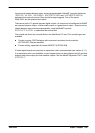
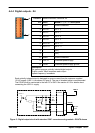
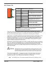
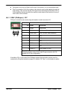
4.5.3 Power - X9
Location Breakout module, connector X9
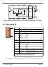
Pin Name Description
1 Vcc
+
5
V
s
u
p
p
l
y
s
o
u
r
c
e
f
r
o
m
t
h
e
h
o
s
t
P
C
2 Vcc
+
5
V
supp
l
y
source
f
rom
t
h
e
h
os
t
P
C
3 Encoder V+
P
o
w
e
r
t
o
t
h
e
e
n
c
o
d
e
r
c
o
n
n
e
c
t
o
r
s
4 Encoder V+
P
ower
t
o
t
h
e enco
d
er connec
t
ors
5 GND
D
i
g
i
t
a
l
g
r
o
u
n
d
f
r
o
m
t
h
e
h
o
s
t
P
C
6 GND
D
i
g
i
t
a
l
groun
d
f
rom
t
h
e
h
os
t
P
C
7 USR V+
C
u
s
t
o
m
e
r
p
o
w
e
r
s
u
p
p
l
y
8 USR V+
C
us
t
omer power supp
l
y
9 CGND
C
u
s
t
o
m
e
r
p
o
w
e
r
s
u
p
p
l
y
g
r
o
u
n
d
10 CGND
C
us
t
omer power supp
l
y
groun
d
Description
Connection point for customer power supply USR V+.
Also used to route power to encoders.
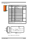
The power connector X9 provides a single connection point for external power supplies.
Access is also provided to the host PC’s 5V supply. Each connection is assigned two pins on
X9 to provide increased wiring capacity. Use wire links to connect power as required.
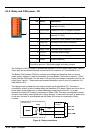
The Encoder V+ and GND connections on X9 are connected internally to the Encoder V+ and
GND pins on connectors X12 to X16. The host PC’s +5V supply can be use to power the
encoders by connecting pin 1 or 2 to pin 3 or 4. A link is provided for this purpose. The total
current requirement of the encoders must not exceed 500mA. Check that the PC’s power
supply is capable of supplying this extra current.
Alternatively, a further external supply (or the USR V+ supply, see below) can be connected to
pins 3 or 4. (Remove any existing link to pin 1 or 2 before connecting an external supply). This
supply must not exceed the PCB track rating of the breakout module which is 3A at 30V.
Check that the encoders have a suitable voltage rating before connecting them to USR V+ or
other external supply .
CAUTION: Encoder power must be connected before operating the system. If the
encoders are not powered when the system is enabled, there will be no
position feedback which could cause violent motion of the motor shaft.
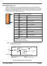
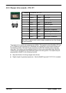
The customer supplied USR V+ is used as the supply for the digital outputs (see sections
4.4.4 and 4.4.5). The USR V+ and CGND connections on connector X9 are connected
internally to the USR V+ and CGND pins on connectors X4, X5 and X8.
Note: The CGND (pin 9 or 10) must be connected to the host PC’s GND (pin 5 or 6).
1
10